Mitsubishi Outlander (2013+). Manual - part 371


  Index      Mitsubishi     Mitsubishi Outlander - service repair manual 2013 year


Search            


Content   ..  369  370  371  372   ..


Mitsubishi Outlander (2013+). Manual - part 371


ON-VEHICLE SERVICE

CVT

23A-54

2. Stall speed is high only when selector lever is in 

the D ranges.

• Forward clutch is slipping

3. Stall speed is high only when the selector lever is 

in the R ranges.

• Reverse brake is slipping

4. Stall speed is low when selector lever is in both D 

and R ranges.

• Malfunction of the torque converter

• Line pressure is low.

• Low engine power

HYDRAULIC PRESSURE TEST

M1231205500567

CAUTION

This test must be performed with the CVT fluid 
temperature within the range of 70 to 80

°C.

1. Start the engine and warm it up until the CVT fluid 

temperature reaches 70 to 80

°C.

2. Stop the engine and block the RH and LH rear 

wheels with the wheel chocks.

AC507202 AB

DR

PRI

PL

FWD

AC507203

REV

AB

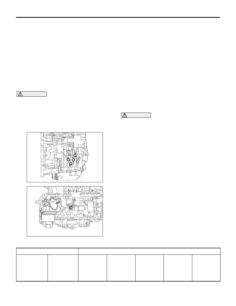
3. Install the following special tools at the hydraulic 

pressure outlet ports shown in the figure.

• Oil pressure gauge <3.0 MPa> (MD998330)

• Joint (MD998331)

• Joint (MB992127)

NOTE: 

.

DR: Torque converter output pressure port
PRI: Primary pressure port
PL: Line pressure port
FWD: Forward clutch pressure port
REV: Reverse brake pressure port

4. Restart the engine.

5. Make sure that no CVT fluid leakage is found at 

the special tool fixing points.

6. Pull the parking brake lever and fully depress the 

brake pedal. (Maintain this operation until 
measurement is completed.)

WARNING

For safety, operators must not stand in front 
of and at the rear of the vehicle during this 
test. 

7. Measure the hydraulic pressure at each 

measuring point in the conditions specified in the 
standard hydraulic pressure table, and check that 
the measurements are within the standard value.

8. If not within the standard value, take necessary 

steps according to the hydraulic pressure test 
diagnosis table.

9. Stop the engine.

10.Replace the O-rings on the plugs for each 

pressure port.

11.Remove the special tools and fit the plugs in the 

hydraulic pressure ports.

12.Install the plugs. Then, start the engine and check 

that no CVT fluid leakage is found around the 
plugs.

Standard hydraulic pressure table

Measuring conditions

Standard hydraulic pressure (MPa)

Selector lever 
position

Engine speed

Forward 
clutch 
pressure 
[Pressure at 
FWD]

Reverse 
brake 
pressure 
[Pressure at 
REV]

Primary 
pressure 
[Pressure at 
PRI]

Line pressure 
[Pressure at 
PL]

Torque 
converter 
[Pressure at 
DR]

ON-VEHICLE SERVICE

CVT

23A-55

Hydraulic pressure test diagnosis table

Symptom

Faulty part

Hydraulic pressure is high at all 
measuring points.

Incorrect measuring method

Hydraulic pressure is low at all measuring 
points.

Malfunction of oil pump
Clogged oil strainer
Clogged oil cooler
Malfunction in valve body assembly
Improper installation of valve body assembly

Only forward clutch pressure is abnormal. Malfunction in valve body assembly

Improper installation of valve body assembly
Faulty seal ring A

Only reverse brake pressure is abnormal. Malfunction in valve body assembly

Improper installation of valve body assembly

Only primary pressure is abnormal

Malfunction in valve body assembly
Improper installation of valve body assembly

Only line pressure is abnormal.

Malfunction in valve body assembly
Improper installation of valve body assembly

Only torque converter output pressure is 
abnormal

Malfunction in valve body assembly
Improper installation of valve body assembly
Malfunction of torque converter
Faulty seal ring B

Seal ring location

AC509098AB

A

B

P

Idling

0

0

0.1 

− 1.5

0.5 

− 1.5

0.1 

− 1.0

R

0

0.5 

− 1.0

0.1 

− 1.5

0.5 

− 1.5

0.1 

− 1.0

N

0

0

0.1 

− 1.5

0.5 

− 1.5

0.1 

− 1.0

D

0.5 

− 1.0

0

0.1 

− 1.5

0.5 

− 1.5

0.1 

− 1.0

Ds <Vehicles 
without paddle 
shift>

0.5 

− 1.0

0

0.1 

− 1.5

0.5 

− 1.5

0.1 

− 1.0

L

0.5 

− 1.0

0

0.1 

− 1.5

0.5 

− 1.5

0.1 

− 1.0

Measuring conditions

Standard hydraulic pressure (MPa)

ON-VEHICLE SERVICE

CVT

23A-56

SELECTOR LEVER OPERATION CHECK

M1231202900425

1. Put on the parking brake.

ACC00042

P

R

N

D

L

P

R

N

D Ds

L

 : Turn the ignition switch to the 

            "ON" position, and operate the lever 

          while depressing the brake pedal.

AB

 : Only lever operating

 <Vehicles with

paddle shift>

 : Automatic return

 <Vehicles without

paddle shift>

2. Move the selector lever to every range and check 

that the lever moves smoothly with secure feel of 
engagement.

3. Make sure that the engine starts when the 

selector lever is in the "N" or "P" range, and does 
not start when the selector lever is in other range.

4. Start the engine. Release the parking brake.

5. Make sure that the vehicle moves forward when 

the selector lever is moved to "D", "Ds" range, or 
to the "L" range. Also make sure that the vehicle 
moves backward when the selector lever is 
moved from the "N" to "R" range.

6. Stop the engine.

7. Turn ON the ignition switch, and move the 

selector lever from the P to R range. Check that 
the backup lamp comes on at this time.

NOTE: Since the vehicle is equipped with the 
CVT wrong-operation preventive device, the 
selector lever cannot be moved out of the "P" 
position without depressing the brake pedal after 
turning "ON" the ignition switch.

ON-VEHICLE SERVICE

CVT

23A-57

SHIFT LOCK MECHANISM CHECK

M1232100300542

SYSTEM CHECK

Inspection 
procedure

Check condition

Items to be checked 
(Normal condition)

Possible cause of abnormality

1

Brake pedal not 
depressed

Ignition switch 
position: Other 
than "ON"

The selector lever 
cannot be moved out 
of the "P" position

• Abnormality in the shift lock 

link (stuck, disengaged, 
broken, etc.)

• Abnormality in the electrical 

circuit

2

Brake pedal 
depressed

• Abnormality in the electrical 

circuit

3

Brake pedal not 
depressed

Ignition switch 
position: "ON"

• Abnormality in the shift lock 

link (stuck, disengaged, 
broken, etc.)

• Abnormality in the electrical 

circuit

4

Brake pedal 
depressed

The selector lever can 
be moved from the "P" 
position to other 
positions smoothly.

• Abnormality in the shift lock 

link (stuck, disengaged, 
broken, etc.)

• Abnormality in the electrical 

circuit

5

Shift lock release 
switch pressed

• Abnormality in the shift lock 

link (stuck, disengaged, 
broken, etc.)

6

Brake pedal 
depressed / not 
depressed

The selector lever can 
be moved from the "R" 
position to the "P" 
position smoothly.

• Abnormality in the shift lock 

link (stuck, disengaged, 
broken, etc.)

COMPONENT PARTS CHECK

SHIFT LOCK LINK

Check each part for damage and disengagement.

SHIFT LOCK SOLENOID

ACB05437

9

3

2

1
5 6 7 8

4

10

AB

Selector lever assembly

1. Measure the resistance between terminal No.3 

and No.7 of the selector lever assembly 
connector.

Standard value: 24 

± 1.2 

2. When the resistance is outside the standard 

value, replace the selector lever assembly.


Content   ..  369  370  371  372   ..