Mitsubishi Outlander (2013+). Manual - part 369
TROUBLESHOOTING
CVT
23A-46
33
INHR
Inhibitor switch R
• Ignition switch: ON
• Selector lever position: R
System voltage
• Ignition switch: ON
• Selector lever position: other than R
1 V or less
34
INHN
Inhibitor switch N
• Ignition switch: ON
• Selector lever position: N
System voltage
• Ignition switch: ON
• Selector lever position: Other than N
1 V or less
35
INHS
Ds position switch
<Vehicles without
paddle shift>
• Ignition switch: ON
• Selector lever position: Ds, L
1 V or less
• Ignition switch: ON
• Selector lever position: Other than Ds
System voltage
36
SECS
Secondary pulley speed
sensor
• Selector lever position: D
• Drive at a constant speed of approx. 20
km/h
• Use an oscilloscope to measure the
voltage between the terminals No. 36
and No. 48.
Oscilloscope
inspection
procedure
(Refer to
.)
37
PRMS
Primary speed sensor
• Selector lever position: D
• Drive at a constant speed of approx. 20
km/h
• Use an oscilloscope to measure the
voltage between the terminals No. 37
and No. 48.
Oscilloscope
inspection
procedure
(Refer to
.)
39
LRPS
Secondary pressure
sensor
• Engine: Idling
• Selector lever position: N
Approx. 1.0 V
40
SPM1
Stepper motor A
Within 2 seconds after the ignition switch
is turned to the ON position
Pulse width: 30
ms
41
SPM2
Stepper motor B
Within 2 seconds after the ignition switch
is turned to the ON position
Pulse width: 10
ms
45
INHD
Inhibitor switch D
• Ignition switch: ON
• Selector lever position: D
System voltage
• Ignition switch: ON
• Selector lever position: other than D
1 V or less
46
INHL
Inhibitor switch L
• Ignition switch: ON
• Selector lever position: Ds, L <Vehicles
without paddle shift>
System voltage
• Ignition switch: ON
• Selector lever position: other than L
1 V or less
48
SGND
Sensor earth
Always
1 V or less
49
SSPW
Sensor power supply
Ignition switch: ON
5.0 V
50
SPWR
CVT fluid temperature
sensor
• Ignition switch: ON
• CVT fluid temperature: 20°C
Approx. 2.0 V
• Ignition switch: ON
• CVT fluid temperature: 80°C
Approx. 1.0 V
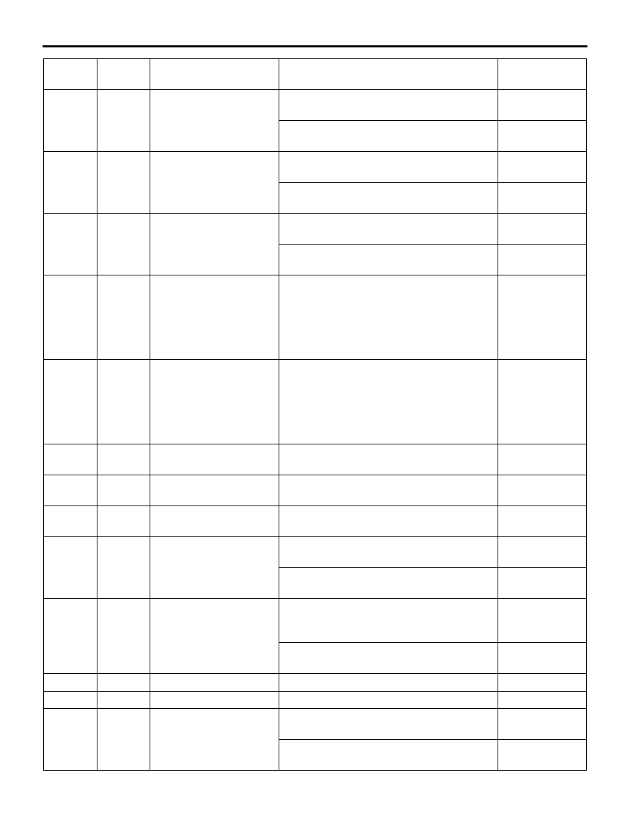
Terminal
No.
Terminal
code
Check item
Check conditions
Standard value