Mitsubishi Outlander (2013+). Manual - part 341


  Index      Mitsubishi     Mitsubishi Outlander - service repair manual 2013 year


Search            


Content   ..  339  340  341  342   ..


Mitsubishi Outlander (2013+). Manual - part 341


EXHAUST PIPE AND MAIN MUFFLER

INTAKE AND EXHAUST

15-10

REMOVAL SERVICE POINTS

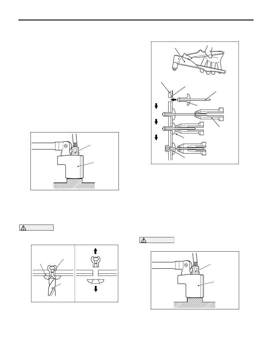
<<A>> OXYGEN SENSOR REMOVAL

AC301966

AB

MB991953

Oxygen sensor

Remove the connection and clamp of oxygen sensor 
connector, and then use special tool oxygen sensor 
wrench (MB991953) to remove the oxygen sensor.

<<B>> RIVET REMOVAL

CAUTION

Be careful not to damage the heat protector with 
the drill.

AC301909AB

Heat
protector

Drill

Rivet

Use a drill (6.0 mm) to make a hole in the rivet to 
break it, and then remove the rivet.

INSTALLATION SERVICE POINTS

>>A<< RIVET INSTALLATION

AC700168

Heart protector

Rivet tool

AB

1

2

3

4

Rivet

Fixing parts

Rivet tool

Rivet

Portion A

Flange

Use a rivet tool shown in the illustration to connect 
the parts with rivets by the following procedures.
1. Insert the rivet into a corresponding location.

2. Set the rivet tool at a portion A of rivet.

3. While pushing the flange surface of the rivet onto 

parts to be fixed with the rivet tool, press the 
handle of the tool.

4. Thin part of portion A of the rivet will be cut off and 

the parts is fixed in position.

>>B<< OXYGEN SENSOR INSTALLATION

CAUTION

AC301966

AB

MB991953

Oxygen sensor

Do not use a sensor that has fallen down.

Tighten the oxygen sensor to the specified torque by 
using special tool oxygen sensor wrench 
(MB991953).

Tightening torque: 44 

± 5 Nm

<<

B

>>

>>

A

<<

10. Rivet

<<

B

>>

>>

A

<<

11. Front floor panel rear heat 

protector
Front exhaust pipe and front 
floor panel front heat protector 
removal steps 

5.

Front exhaust pipe

8.

Seal ring

12. Seal ring
13. Dash panel heat protector

<<

B

>>

>>

A

<<

14. Rivet

<<

B

>>

>>

A

<<

15. Front floor panel front heat 

protector

Centre exhaust pipe and front 
floor panel rear heat protector 
removal steps (Continued)

16-1

GROUP 16

ENGINE 

ELECTRICAL

CONTENTS

CHARGING SYSTEM  . . . . . . . . . . . .

16-2

GENERAL INFORMATION. . . . . . . . . . . . . 

16-2

SERVICE SPECIFICATIONS . . . . . . . . . . . 

16-3

SPECIAL TOOL  . . . . . . . . . . . . . . . . . . . . . 

16-4

ON-VEHICLE SERVICE . . . . . . . . . . . . . . . 

16-6

ALTERNATOR OUTPUT LINE VOLTAGE DROP 
TEST . . . . . . . . . . . . . . . . . . . . . . . . . . . . . . 

16-6

OUTPUT CURRENT TEST. . . . . . . . . . . . . 

16-7

REGULATED VOLTAGE TEST  . . . . . . . . . 

16-9

WAVEFORM CHECK USING AN OSCILLOSCOPE


 . . . . . . . . . . . . . . . . . . . . . . . . . . . . . . . . . . . . . .

16-10

ALTERNATOR ASSEMBLY . . . . . . . . . . . . 

16-13

REMOVAL AND INSTALLATION . . . . . . . . 

16-13

DISASSEMBLY AND REASSEMBLY. . . . . 

16-14

INSPECTION  . . . . . . . . . . . . . . . . . . . . . . . 

16-16

STARTING SYSTEM . . . . . . . . . . . . .

16-18

GENERAL INFORMATION. . . . . . . . . . . . . 

16-18

SERVICE SPECIFICATIONS . . . . . . . . . . . 

16-19

ON-VEHICLE SERVICE . . . . . . . . . . . . . . . 

16-19

STARTER RELAY CONTINUITY CHECK  . 

16-19

STARTER MOTOR ASSEMBLY. . . . . . . . . 

16-20

REMOVAL AND INSTALLATION . . . . . . . . 

16-20

STARTER MOTOR ASSEMBLY INSPECTION


. . . . . . . . . . . . . . . . . . . . . . . . . . . . . . . . . . . . . . 

16-21

DISASSEMBLY AND REASSEMBLY . . . . . 

16-23

INSPECTION. . . . . . . . . . . . . . . . . . . . . . . . 

16-25

IGNITION SYSTEM. . . . . . . . . . . . . . .

16-26

GENERAL INFORMATION . . . . . . . . . . . . . 

16-26

SERVICE SPECIFICATIONS  . . . . . . . . . . . 

16-27

SPECIAL TOOLS  . . . . . . . . . . . . . . . . . . . . 

16-28

ON-VEHICLE SERVICE  . . . . . . . . . . . . . . . 

16-29

IGNITION COIL CHECK . . . . . . . . . . . . . . . 

16-29

SPARK PLUG CHECK AND CLEANING  . . 

16-30

CAMSHAFT POSITION SENSOR CHECK . 

16-31

CRANK ANGLE SENSOR CHECK . . . . . . . 

16-31

DETONATION SENSOR CHECK . . . . . . . . 

16-32

IGNITION COIL . . . . . . . . . . . . . . . . . . . . . . 

16-32

REMOVAL AND INSTALLATION  . . . . . . . . 

16-32

CAMSHAFT POSITION SENSOR  . . . . . . . 

16-33

REMOVAL AND INSTALLATION  . . . . . . . . 

16-33

CRANK ANGLE SENSOR. . . . . . . . . . . . . . 

16-34

REMOVAL AND INSTALLATION  . . . . . . . . 

16-34

DETONATION SENSOR . . . . . . . . . . . . . . . 

16-35

REMOVAL AND INSTALLATION  . . . . . . . . 

16-35

CHARGING SYSTEM

ENGINE ELECTRICAL

16-2

CHARGING SYSTEM

GENERAL INFORMATION

M1161000102153

The charging system uses the alternator output to 
keep the battery charged at a constant level under 
various electrical loads.

OPERATION

AK400075

Voltage

Time

Approximately
14.4 V

AB

Rotation of the excited field coil generates AC volt-
age in the stator.
This alternating current is rectified through diodes to 
DC voltage having a waveform shown in the illustra-
tion.

The average output voltage fluctuates slightly with 
the alternator load condition.
When the ignition switch is turned on, current flows in 
the field coil and initial excitation of the field coil 
occurs. 
When the stator coil begins to generate power after 
the engine is started, the field coil is excited by the 
output current of the stator coil. 
The alternator output voltage rises as the field cur-
rent increases and it falls as the field current 
decreases. When the battery voltage (alternator "S" 
terminal voltage) reaches a regulated voltage of 
approximately 14.4 V, the field current is cut off. 
When the battery voltage drops below the regulated 
voltage, the voltage regulator regulates the output 
voltage to a constant level by controlling the field cur-
rent. 
In addition, when the field current is constant, the 
alternator output voltage rises as the engine speed 
increases.

SYSTEM DIAGRAM

AK604823

Alternator

B

Stator 
coil

Engine-ECU

CAN 
communication

G
S
L
FR

Voltage
regulator

Battery

Field coil

+

-

AB

Charging 
warning lamp

Combination meter

ALTERNATOR SPECIFICATIONS

Item

4B1

Type

Battery voltage sensing

Rated output V/A

12/105

CHARGING SYSTEM

ENGINE ELECTRICAL

16-3

SERVICE SPECIFICATIONS

M1161000301400

Item

Standard value

Limit

Alternator output line voltage drop (at 30 A) V

maximum 0.3

Regulated voltage ambient 
temperature at voltage regulator V

−20°C

14.2 

− 15.4

20

°C

13.9 

− 14.9

60

°C

13.4 

− 14.6

80

°C

13.1 

− 14.5

Output current

70 % of normal output current

Voltage regulator

Electronic built-in type

Item

4B1


Content   ..  339  340  341  342   ..