Mitsubishi Outlander (2013+). Manual - part 332


  Index      Mitsubishi     Mitsubishi Outlander - service repair manual 2013 year


Search            


Content   ..  330  331  332  333   ..


Mitsubishi Outlander (2013+). Manual - part 332


FUEL TANK <4WD>

FUEL SUPPLY

13B-12

FUEL TANK <4WD>

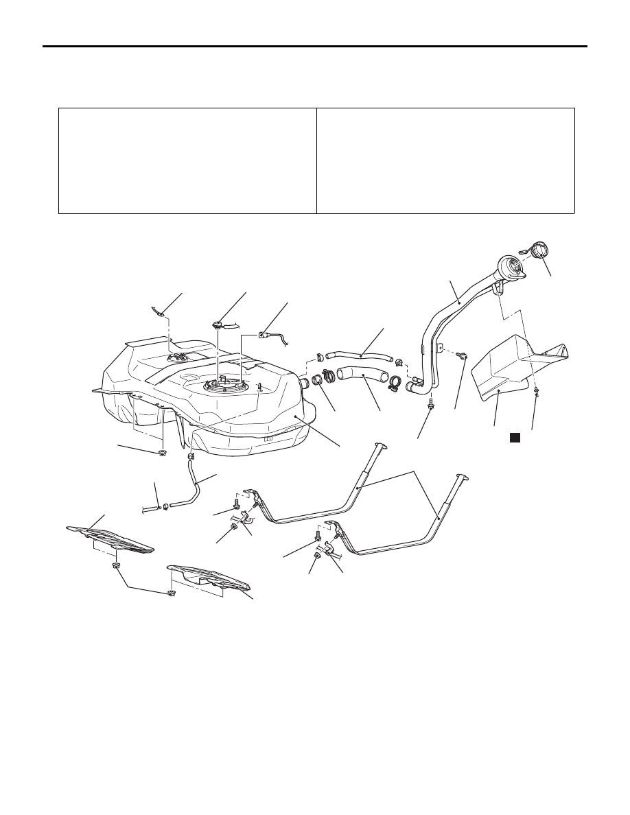
REMOVAL AND INSTALLATION <4WD>

M1135001904061

Pre-removal operation
• Fuel Pump Connector Disconnection (Refer to GROUP 

13A 

− On-vehicle Service, How to Reduce Pressurized 

Fuel Lines ).

• Fuel Draining.

• Propeller Shaft Removal (Refer to GROUP 25 − Propeller 

Shaft ).

• Centre Exhaust Pipe Removal (Refer to GROUP 15 − 

Exhaust Pipe and Main Muffler ).

Post-installation operation
• Centre Exhaust Pipe Removal (Refer to GROUP 15 − 

Exhaust Pipe and Main Muffler ).

• Propeller Shaft Installation (Refer to GROUP 25 − Propel-

ler Shaft ).

• Fuel Refilling.
• Fuel Leak Check (Refer to 

P.13B-5

).

ACB05947

13 ± 2 N·m

13 ± 2 N·m

41 ± 10 N·m

41 ± 10 N·m

22 ± 5 N·m

9

9

10

11

4

8

6

1

2

3

15

12

AB

16

7

5

5

3.5 ± 1.5 N·m

20 ± 5 N·m

20 ± 5 N·m

14

13

N

Removal steps 

Second seat assembly (Refer to 
GROUP 52A 

− Second Seat 

Assembly ).

<<

A

>>

1.

Fuel pump and gauge assembly 
connector

<<

A

>>

>>

C

<<

2.

Fuel main pipe connection

<<

B

>>

3.

Fuel gauge unit connector

4.

Fuel vapour pipe connection

5.

Front floor under cover

>>

B

<<

6.

Fuel filler hose

7.

Fuel shut-off valve

8.

Fuel filler neck breather hose

<<

C

>>

9.

Parking brake rear cable clamp 
connection

Differential mount bracket 
mounting bolt

<<

C

>>

10. Fuel tank band

<<

C

>>

11. Fuel tank assembly
12. Fuel tank cap

<<

D

>>

>>

A

<<

13. Rivet

<<

D

>>

>>

A

<<

14. Filler neck protector
15. Fuel filler neck assembly
16. Fuel vapour hose

Removal steps (Continued)

FUEL TANK <4WD>

FUEL SUPPLY

13B-13

REMOVAL SERVICE POINTS

<<A>> FUEL PUMP AND GAUGE ASSEM-
BLY CONNECTOR/SPARE CONNEC-
TOR/FUEL MAIN PIPE DISCONNECTION

ACB05942

Floor inspection lid (RH)

AB

1. Remove the floor inspection lid (LH).

ACB05941AB

Fuel pump and gauge
assembly connector

2. Disconnect the fuel pump and gauge assembly 

connector.

AC606017

Retainer

Flat-tip
screwdriver

Fuel main pipe

AG

Fuel pump and 
gauge assembly

3. Insert a flat-tipped screwdriver (6 mm wide and 1 

mm thick) into the retainer of the fuel main pipe 
connector.

CAUTION

When pushing up the retainer of the fuel main 
pipe connector, pay attention to avoid damage to 
the retainer.

AC606018

Retainer

Flat-tip screwdriver

Fuel main pipe

AG

Fuel pump and 
gauge assembly

4. Turn the flat-tipped screwdriver inserted into the 

retainer by 90 degrees to push up the retainer and 
unlock the fuel main pipe connector.

5. Disconnect the fuel main pipe from the fuel pump 

and gauge assembly.

<<B>> FUEL GAUGE UNIT CONNECTOR 
DISCONNECTION

ACB05943

Floor inspection lid (RH)

AB

1. Remove the floor inspection lid (RH).

ACB05944AB

Fuel gauge 
unit connector

2. Disconnect the fuel gauge unit connector.

<<C>> DIFFERENTIAL MOUNT BRACKET 
MOUNTING BOLT/FUEL TANK 
BAND/FUEL TANK ASSEMBLY REMOVAL

ACB05891AB

Lower

Tilt

Fuel tank
assembly

Differential 
carrier assembly

Towards front 
of vehicle

FUEL TANK <4WD>

FUEL SUPPLY

13B-14

1. Remove the fuel tank, continuously checking that 

it does not make contact with the differential 
carrier assembly.

AC506457AB

Fuel tank 
assembly

2. Hold the fuel tank assembly with the transmission 

jack, and remove the connecting bolts of fuel tank 
band and the connecting nuts of fuel tank 
assembly.

3. Remove the fuel tank assembly in the tilt direction, 

paying attention not to bump it against the 
differential carrier assembly.

<<D>> RIVET/FUEL FILLER NECK 
PROTECTOR REMOVAL

CAUTION

Be careful not to damage the fuel filler neck pro-
tector with the drill.

AC606123

Fuel filler neck 
protector

Rivet

Drill

AE

Use a drill (6.0 mm) to make a hole in the rivet to 
break it, and then remove the rivet.

INSTALLATION SERVICE POINTS

>>A<< FUEL FILLER NECK PROTEC-
TOR/RIVET INSTALLATION

AC700168

Fuel filler neck protector

Rivet tool

AE

1

2

3

4

Rivet

Fixing parts

Rivet tool

Rivet

Portion A

Flange

Use a rivet tool shown in the illustration to connect 
the parts with rivets by the following procedures.
1. Insert the rivet into a corresponding location.

2. Set the rivet tool at a portion A of rivet.

3. While pushing the flange surface of the rivet onto 

parts to be fixed with the rivet tool, press the 
handle of the tool.

4. Thin part of portion A of the rivet will be cut off and 

the part is fixed in position.

>>B<< FUEL FILLER HOSE CONNECTION

AC707593AI

4.5 ± 1.5 mm

Hose clamp

After connecting the fuel filler hose, tighten the bolts 
of hose clamp so that the tightening dimension is 4.5 
± 1.5 mm.

FUEL TANK <4WD>

FUEL SUPPLY

13B-15

>>C<< FUEL MAIN PIPE CONNECTION

AC606019

Retainer

Fuel main pipe

AB

1. Pull up the retainer of fuel main pipe to unlock 

before installing.

CAUTION

• When pushing in the retainer of the fuel main 

pipe connector, pay attention to avoid dam-
age to the retainer.

AC606020

Retainer

Fuel main pipe

AJ

Fuel pump and 
gauge assembly

After the installation of the fuel main pipe, 
slightly pull the fuel main pipe to check that it 
is connected securely. At this time, also 
check that there is approximately 1 mm play.

2. Install the fuel main pipe to the fuel pump and 

gauge assembly securely and push in the retainer 
of the fuel main pipe connector to lock the fuel 
main pipe and fuel pump and gauge assembly.


Content   ..  330  331  332  333   ..