Mitsubishi Outlander (2013+). Manual - part 331


  Index      Mitsubishi     Mitsubishi Outlander - service repair manual 2013 year


Search            


Content   ..  329  330  331  332   ..


Mitsubishi Outlander (2013+). Manual - part 331


FUEL TANK <2WD>

FUEL SUPPLY

13B-8

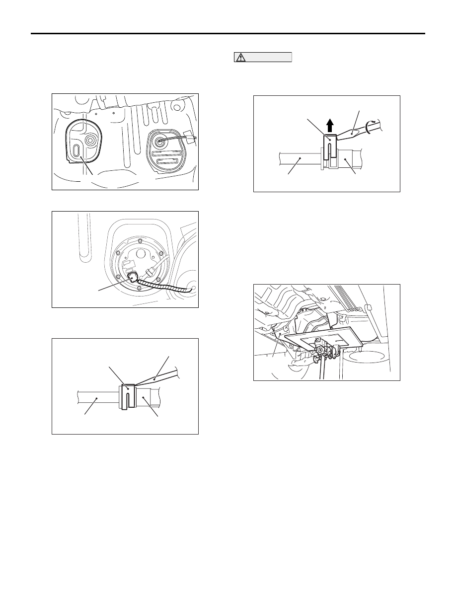
REMOVAL SERVICE POINTS

<<A>> FUEL PUMP AND GAUGE ASSEM-
BLY CONNECTOR/SPARE CONNEC-
TOR/FUEL MAIN PIPE DISCONNECTION

ACB05942

Floor inspection lid (RH)

AB

1. Remove the floor inspection lid (LH).

ACB05941AB

Fuel pump and gauge
assembly connector

2. Disconnect the fuel pump and gauge assembly 

connector and spare connector.

AC606017

Retainer

Flat-tip
screwdriver

Fuel main pipe

AG

Fuel pump and 
gauge assembly

3. Insert a flat-tip screwdriver (6 mm wide and 1 mm 

thick) into the retainer of the fuel main pipe 
connector.

CAUTION

When pushing up the retainer of the fuel main 
pipe connector, pay attention to avoid damage to 
the retainer.

AC606018

Retainer

Flat-tip screwdriver

Fuel main pipe

AG

Fuel pump and 
gauge assembly

4. Turn the flat-tip screwdriver inserted into the 

retainer by 90 degrees to push up the retainer and 
unlock the fuel main pipe connector.

5. Disconnect the fuel main pipe from the fuel pump 

and gauge assembly.

<<B>> FUEL TANK BAND/FUEL TANK 
ASSEMBLY REMOVAL

AC506457AB

Fuel tank 
assembly

1. Hold the fuel tank assembly with the transmission 

jack, and remove the connecting bolts of fuel tank 
band and the connecting nuts of fuel tank 
assembly.

2. Remove the fuel tank assembly.

FUEL TANK <2WD>

FUEL SUPPLY

13B-9

<<C>> RIVET/FUEL FILLER NECK 
PROTECTOR REMOVAL

CAUTION

Be careful not to damage the fuel filler neck pro-
tector with the drill.

AC606123

Fuel filler neck 
protector

Rivet

Drill

AE

Use a drill (6.0 mm) to make a hole in the rivet to 
break it, and then remove the rivet.

INSTALLATION SERVICE POINTS

>>A<< FUEL FILLER NECK PROTEC-
TOR/RIVET INSTALLATION

AC700168

Fuel filler neck protector

Rivet tool

AE

1

2

3

4

Rivet

Fixing parts

Rivet tool

Rivet

Portion A

Flange

Use a rivet tool shown in the illustration to connect 
the parts with rivets by the following procedures.
1. Insert the rivet into a corresponding location.

2. Set the rivet tool at a portion A of rivet.

3. While pushing the flange surface of the rivet onto 

parts to be fixed with the rivet tool, press the 
handle of the tool.

4. Thin part of portion A of the rivet will be cut off and 

the part is fixed in position.

>>B<< FUEL FILLER HOSE CONNECTION

AC707593AI

4.5 ± 1.5 mm

Hose clamp

After connecting the fuel filler hose, tighten the bolts 
of hose clamp so that the tightening dimension is 4.5 
± 1.5 mm.

>>C<< FUEL MAIN PIPE CONNECTION

AC606019

Retainer

Fuel main pipe

AB

1. Pull up the retainer of fuel main pipe to unlock 

before installing.

CAUTION

• When pushing in the retainer of the fuel main 

pipe connector, pay attention to avoid dam-
age to the retainer.

AC606020

Retainer

Fuel main pipe

AJ

Fuel pump and 
gauge assembly

After the installation of the fuel main pipe, 
slightly pull the fuel main pipe to check that it 
is connected securely. At this time, also 
check that there is approximately 1 mm play.

FUEL TANK <2WD>

FUEL SUPPLY

13B-10

2. Install the fuel main pipe to the fuel pump and 

gauge assembly securely and push in the retainer 
of the fuel main pipe connector to lock the fuel 
main pipe and fuel pump and gauge assembly.

DISASSEMBLY AND REASSEMBLY

M1135006800692

ACB05946

2.5 ± 0.4 N·m

5.0 ± 1.0 N·m

1

2

3

5

AB

4

N

Removal steps 

1.

Fuel pump bracket plate

<<

A

>>

>>

A

<<

2.

Fuel pump and gauge assembly

3.

Fuel pump and gauge assembly 
gasket

4.

Fuel tank lower protector

5.

Fuel tank

DISASSEMBLY SERVICE POINTS

<<A>> FUEL PUMP AND GAUGE ASSEM-
BLY REMOVAL

CAUTION

Pay attention not to damage the gauge unit and 
the float of fuel pump and gauge assembly when 
removing it from the fuel tank.
Remove the fuel pump and gauge assembly from the 
fuel tank.

REASSEMBLY SERVICE POINTS

>>A<< FUEL PUMP AND GAUGE ASSEM-
BLY INSTALLATION

CAUTION

• Pay attention not to damage the gauge unit 

and the float of fuel pump and gauge assem-
bly when installing it to the fuel tank.

• When installing the fuel pump and gauge 

assembly to the fuel tank, check that the 
gauge moving area moves smoothly.

Install the fuel pump and gauge assembly to the fuel 
tank.

FUEL TANK <2WD>

FUEL SUPPLY

13B-11

DISASSEMBLY AND ASSEMBLY

M1135004601822

FUEL PUMP AND GAUGE ASSEMBLY

NOTE: For installation and removal, refer to On-vehi-
cle Service, Fuel Pump Module Replacement (Refer 
to 

P.13B-2

).

ACC00457

1

2

3

4

5

6

7

8

14

N

10

11

N

N

12

9

N

13

AB

N

N

N

N

N

N

N

Disassembly steps 

1.

Fuel gauge unit

2.

Clip

3.

Spring

4.

Fuel pump wiring harness

5.

Fuel filter

6.

Fuel pump assembly

>>

A

<<

7.

O-ring

8.

Spacer

9.

Fuel pressure regulator

>>

A

<<

10. O-ring

>>

A

<<

11. O-ring

12. Spacer
13. Bracket
14. Fuel flange and filter assembly

ASSEMBLY SERVICE POINT

>>A<< O-RING INSTALLATION

To avoid twisting and damage, apply gasoline before 
installation of the O-ring.

Disassembly steps 


Content   ..  329  330  331  332   ..