Mitsubishi Outlander (2013+). Manual - part 328
AC506793
AB
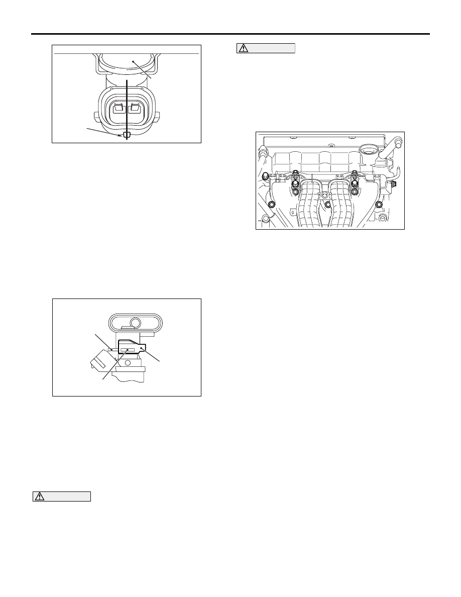
Fuel injector
Projection
INJECTOR
MULTIPOINT FUEL INJECTION (MPI)
13A-193
2. Turning the fuel injector assembly to right and left,
install it to the fuel delivery pipe with care not to
damage the O-ring. After the installation, check
for its smooth rotation. At this time, check that the
projection part of the fuel injector assembly is in
the centre.
3. If the rotation is not smooth, the O-ring may be
caught. Remove the fuel injector assembly and
check the O-ring for damage. After this, re-insert it
to the fuel delivery pipe and check for its smooth
rotation.
>>D<< FUEL INJECTOR SUPPORT
INSTALLATION
AC312109
AC
Fuel delivery
pipe brim
Fuel injector
support
Fuel injector
groove
Install the fuel injector support to the fuel injector
groove and fuel delivery pipe brim, and fix the fuel
injector assembly and fuel delivery pipe.
>>E<< FUEL DELIVERY PIPE AND FUEL
INJECTOR
ASSEMBLY/BRACKET/INJECTOR
PROTECTOR REAR INSTALLATION
CAUTION
When applying the engine oil, make sure not to
allow the engine oil to enter the inlet manifold
inside.
1. Apply a small amount of new engine oil to the
O-ring at the end of fuel injector assembly.
CAUTION
When installing the fuel delivery pipe and fuel
injector assembly to the inlet manifold, pay atten-
tion to avoid damage to the O-ring at the end of
the fuel injector assembly.
2. Install the fuel delivery pipe and fuel injector
assembly to the inlet manifold.
3. Install the bracket and injector protector rear.
ACB05830
AB
10
3
5
7
1
6
4
2
9
8
11
4. Loosen the inlet manifold mounting bolts and nuts
(Bolts and nuts 1, 2, 3 and 9 shown in the figure).
5. Loosen the inlet manifold stay mounting bolts
(Refer to GROUP 15
− Inlet Manifold ).
6. Temporarily tighten the mounting bolts and nuts of
the inlet manifold, bracket, fuel delivery pipe and
injector protector rear to the specified torque in
the order of number shown in the figure.
Tightening torque: 3.5
± 1.5 N⋅m
7. Tighten the mounting bolts of the fuel delivery
pipe, and the mounting bolts and nuts of the
bracket, injector protector rear and inlet manifold
to the specified torque in the order of number
shown in the figure.
Tightening torque: 20
± 2 N⋅m
8. Tighten the inlet manifold stay mounting bolts to
the specified torque (Refer to GROUP 15
− Inlet
Manifold ).
Tightening torque: 20
± 2 N⋅m