Mitsubishi Outlander (2013+). Manual - part 261


  Index      Mitsubishi     Mitsubishi Outlander - service repair manual 2013 year


Search            


Content   ..  259  260  261  262   ..


Mitsubishi Outlander (2013+). Manual - part 261


ENGINE ASSEMBLY

ENGINE MECHANICAL

11A-67

2. Remove special tools engine hanger (MB991928 

or MB991895) and engine hanger plate 
(MB992853) which was installed for supporting 
the engine assembly when the transmission 
assembly was removed (Refer to GROUP 23A 

− 

Transmission Assembly ).

3. Operate a garage jack so that the engine weight is 

not applied to the engine mounting bracket, and 
remove the engine mounting bracket.

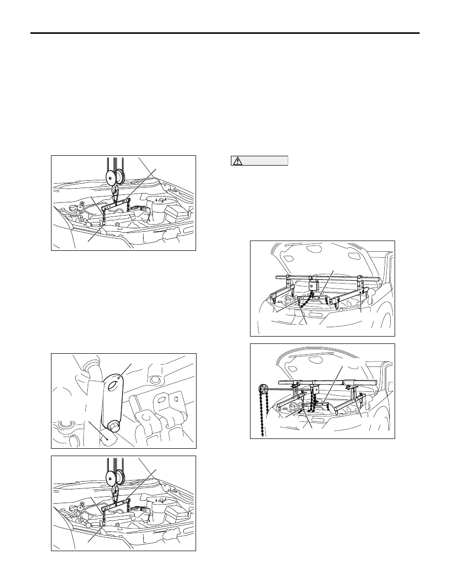
<<E>> ENGINE ASSEMBLY REMOVAL

AC506787

MB991527

MB991454

AB

MB991956

After checking that all cables, hoses and wiring har-
ness connectors and so on are disconnected from 
the engine, lift the engine assembly slowly with the 
chain block to remove the engine assembly upward 
from the engine compartment.

INSTALLATION SERVICE POINTS

>>A<< ENGINE ASSEMBLY INSTALLA-
TION

AC600152AB

MB991956

Oil control 
valve 
(inlet side)

AC506787

MB991527

MB991454

AB

MB991956

1.  Install special tool engine hanger plate 

(MB991956) to the cylinder head, and set special 
tool hanger (MB991527) and the chains of special 
tool engine hanger balancer (MB991454) to the 
engine assembly to hold the engine assembly.

2. Install the engine assembly, being careful not to 

pinch the cables, hoses, or wiring harness 
connectors.

>>B<< ENGINE MOUNTING BRACKET 
INSTALLATION

CAUTION

When supporting the engine and transmission 
assembly with a garage jack, be careful not to 
deform the engine oil pan.

1. Place a garage jack against the engine oil pan 

with a piece of wood in between, and install the 
engine mounting bracket while adjusting the 
position of the engine.

AC506487

AD

MB991527

MB991454

MB991928

MB991956

AC506484

MB991527

AD

MB991454

MB991956

MB991895

2. Install special tool engine hanger (MB991928 or 

MB991895) which is used during installation of 
transmission assembly to hold the engine 
assembly (Refer to GROUP 23A 

− Transmission 

Assembly ).

3. Remove the garage jack which supports the 

engine assembly.

ENGINE ASSEMBLY

ENGINE MECHANICAL

11A-68

>>C<< EARTH CABLE CONNECTION

AC606264

AB

15˚

15˚

1. Install the earth cable in the direction shown in the 

illustration.

2. Tighten the alternator mounting bolt to the 

specified torque.

Tightening torque: 44 

± 10 Nm

>>D<< A/C COMPRESSOR AND CLUTCH 
ASSEMBLY INSTALLATION

AC506759

AK

1

2

3

A/C compressor 
and clutch assembly

Tighten A/C compressor and clutch assembly mount-
ing bolts to the specified torque in the order of 
number shown in the illustration.

Tightening torque: 23 

± 6 Nm

>>E<< FUEL HIGH-PRESSURE HOSE 
INSTALLATION

CAUTION

After connecting the fuel high-pressure hose, 
slightly pull it in the pull-out direction to check 
that it is installed firmly. In addition, check that 
there is approximately 3-mm play. After the 
check, install the stopper securely.

AC301864AB

3 mm

Fuel 
high-pressure 
hose

Fuel line pipe
(Engine oil applied)

AC301863AB

Stopper

Apply a small amount of engine oil to the fuel line 
pipe, and install the fuel high-pressure hose.

>>F<< RADIATOR HOSE/HOSE CLIP 
CONNECTION

CAUTION

Never reuse the hose clip whose claw is broken 
off to prevent the rusting.

1. Make mating mark on a new hose clip in the same 

position as the remove one.

AC606082

Protrusion

Pipe, fitting, or etc.

AU

Mating marks

ENGINE ASSEMBLY

ENGINE MECHANICAL

11A-69

2. Insert the radiator hose until the protrusion of the 

pipe.

3. Align the mating marks on the radiator hose and 

hose clip.

4. Remove the hose clip claw and shorten the hose 

clip, then install the radiator hose.

11B-1

GROUP 11B

ENGINE OVERHAUL

CONTENTS

GENERAL SPECIFICATIONS . . . . . .

11B-2

SERVICE SPECIFICATIONS. . . . . . .

11B-2

REWORK DIMENSIONS . . . . . . . . . .

11B-3

TORQUE SPECIFICATIONS . . . . . . .

11B-3

SEALANTS  . . . . . . . . . . . . . . . . . . . .

11B-6

SPECIAL TOOLS. . . . . . . . . . . . . . . .

11B-7

ALTERNATOR AND IGNITION SYSTEM


. . . . . . . . . . . . . . . . . . . . . . . . . . . . . . . . . 

11B-10

REMOVAL AND INSTALLATION . . . . . . . . 

11B-10

THROTTLE BODY . . . . . . . . . . . . . . .

11B-13

REMOVAL AND INSTALLATION . . . . . . . . 

11B-13

INLET MANIFOLD AND FUEL SYSTEM


. . . . . . . . . . . . . . . . . . . . . . . . . . . . . . . . . 

11B-14

REMOVAL AND INSTALLATION . . . . . . . . 

11B-14

EXHAUST MANIFOLD. . . . . . . . . . . .

11B-17

REMOVAL AND INSTALLATION . . . . . . . . 

11B-17

WATER HOSE AND PIPE . . . . . . . . .

11B-19

REMOVAL AND INSTALLATION . . . . . . . . 

11B-19

OIL PAN AND TIMING CHAIN CASE

11B-21

REMOVAL AND INSTALLATION  . . . . . . . . 

11B-21

TIMING CHAIN . . . . . . . . . . . . . . . . . .

11B-26

REMOVAL AND INSTALLATION  . . . . . . . . 

11B-26

INSPECTION. . . . . . . . . . . . . . . . . . . . . . . . 

11B-29

CAMSHAFT  . . . . . . . . . . . . . . . . . . . .

11B-32

REMOVAL AND INSTALLATION  . . . . . . . . 

11B-32

INSPECTION. . . . . . . . . . . . . . . . . . . . . . . . 

11B-35

CYLINDER HEAD AND VALVES. . . .

11B-37

REMOVAL AND INSTALLATION  . . . . . . . . 

11B-37

INSPECTION. . . . . . . . . . . . . . . . . . . . . . . . 

11B-40

OIL PUMP CHAIN <4B11> . . . . . . . . .

11B-43

REMOVAL AND INSTALLATION  . . . . . . . . 

11B-43

BALANCER CHAIN <4B12>  . . . . . . .

11B-47

REMOVAL AND INSTALLATION  . . . . . . . . 

11B-47

PISTON AND CONNECTING ROD  . .

11B-53

REMOVAL AND INSTALLATION  . . . . . . . . 

11B-53

INSPECTION. . . . . . . . . . . . . . . . . . . . . . . . 

11B-58

CRANKSHAFT AND CYLINDER BLOCK


 . . . . . . . . . . . . . . . . . . . . . . . . . . . . . . . . .

11B-59

REMOVAL AND INSTALLATION  . . . . . . . . 

11B-59

INSPECTION. . . . . . . . . . . . . . . . . . . . . . . . 

11B-62


Content   ..  259  260  261  262   ..