Mitsubishi Outlander (2013+). Manual - part 206
LIGHTING
CHASSIS ELECTRICAL
54A-6
• For the low-beam of the headlamp, the headlamp
manual levelling system <Vehicles with halogen
type headlamp> (Refer to .) and the headlamp
automatic levelling system <Vehicles with dis-
charge type headlamp> (Refer to .) have been
adopted so that the height adjustment of the opti-
cal axis can be performed depending on the vehi-
cle load status.
• There are three types of front fog lamps; front fog
lamp (vehicles without daytime running lamp),
front fog lamp (vehicles with daytime running
lamp) and daytime running lamp. These are
installed on the front bumper.
• The rear fog lamp and back-up lamp have been
installed to the rear bumper.
• Two types of the side turn-signal lamp have been
established: the one attached to the fender panel
and the one integrated into the door mirror.
• The rear combination lamp are integrated with
the stop/tail lamp and rear turn-signal lamp.
• The LED-type high-mounted stop lamp have
been integrated into the tailgate.
• The licence plate lamp have been installed to
above the licence plate.
• The lighting system is provided with headlamp
automatic-shutdown function, auto lamp function,
welcome light function and coming home light
function (Refer to
P.54A-12
).
• For the flasher timer function of turn-signal lamp,
the comfort flasher function has been adopted to
improve the operability when changing the lane.
When the turn-signal lamp switch (lighting switch)
is operated for a short time, this function flashes
the turn-signal lamp of the operated direction
three times (Refer to
P.54A-12
).
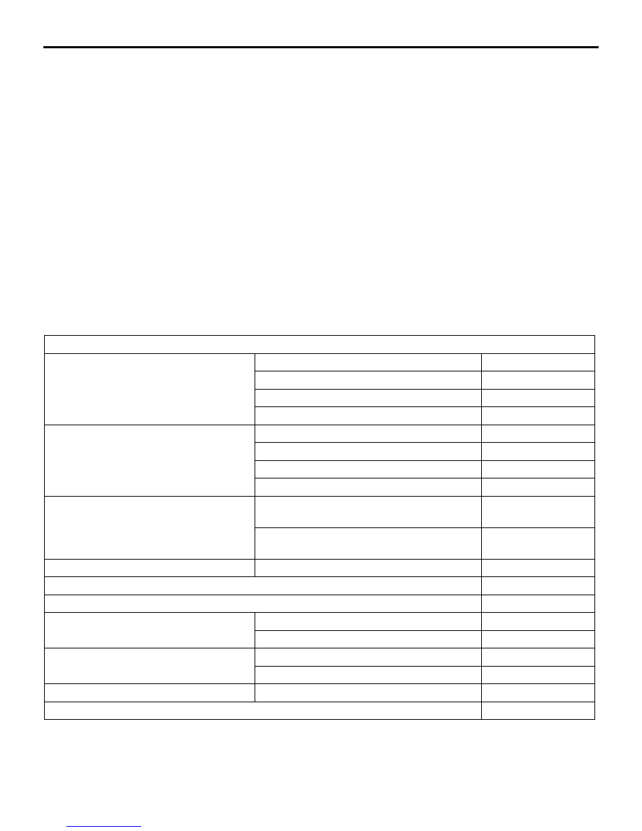
Specifications
NOTE: The brackets ( ) show the bulb type.
Item
Headlamp assembly <Vehicles with
halogen type headlamp>
High-beam W
60 (HB3)
Low-beam W
55 (H7)
Position lamp W
5 (W5W)
Front turn-signal lamp W
21 (PY21W)
Headlamp assembly <Vehicles with
discharge type headlamp>
High-beam W
60 (HB3)
Low-beam W
35 (D4S)
Position lamp W
5 (W5W)
Front turn-signal lamp W
21 (PY21W)
Front fog lamp
Front fog lamp (vehicles without daytime
running lamp) W
55 (H11)
Front fog lamp (vehicles with daytime
running lamp) W
35 (H8)
Daytime running lamp
Daytime running lamp W
13 (P13W)
Rear fog lamp W
21 (W21W)
Back-up lamp W
21 (W21W)
Side turn-signal lamp
Fender panel type W
5
Door mirror type
LED type
Rear combination lamp
Stop/tail W
21 (P21/5W)
Rear turn-signal W
21 (PY21W)
High-mounted stop lamp
Integrated in tailgate spoiler
LED type
Licence plate lamp W
5 (W5W)
manuals search engine