Mitsubishi Outlander (2013+). Manual - part 165


  Index      Mitsubishi     Mitsubishi Outlander - service repair manual 2013 year


Search            


Content   ..  163  164  165  166   ..


Mitsubishi Outlander (2013+). Manual - part 165


ACTIVE STABILITY CONTROL SYSTEM (ASC)

ACTIVE STABILITY CONTROL SYSTEM (ASC)

35C-12

When the driving wheels slip on the slippery road 
surface, TCL applies the brake automatically, sends 
the signal requesting engine speed reduction to the 
engine-ECU, and prevents the loss of the driving 
force resulting from the slippage of the driving wheel.

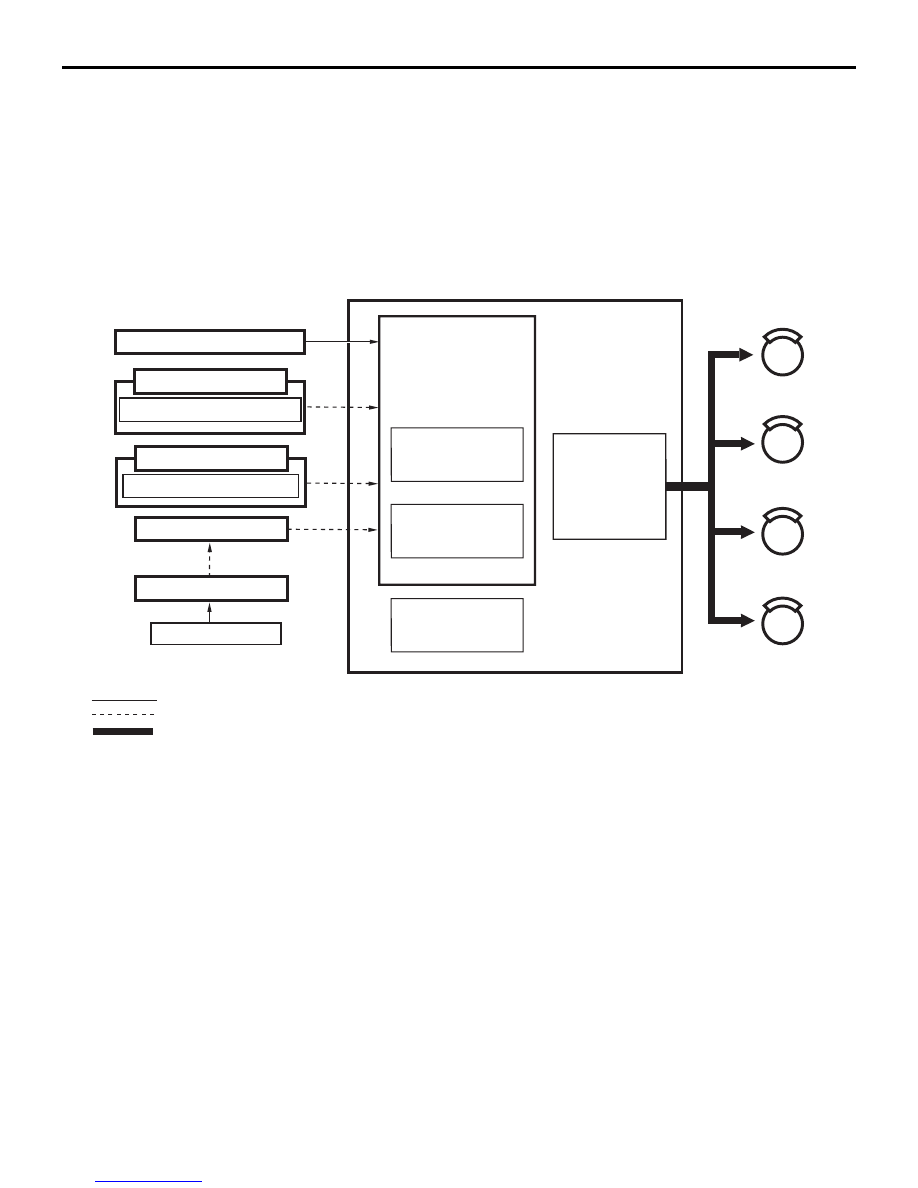
Hill START ASSIST (HSA) FUNCTION

System configuration

When the vehicle has completely stopped on a steep 
uphill by the service brake, ASC-ECU judges 
whether or not start the HSA function control in 
accordance with the signals (ETACS-ECU, 
CVT-ECU, G & yaw rate sensor, brake fluid pressure 
sensor, engine-ECU, wheel speed sensor).

ACB06022

gear position information

CVT-ECU

Parking brake switch

ETACS-ECU

engine related information

Engine-ECU

: Hardwire-line
: CAN line
: Brake-line

Wheel speed sensor

Combination meter

FL

FR

RL

RR

AB

Hydraulic unit

ASC-ECU

Master cylinder 
pressure sensor

G and yaw rate 
sensor

HSA control

Brake fluid 
currently 
supplied to each
wheel cylinder 
is controlled.

Downloaded from 

www.Manualslib.com


manuals search engine


ACTIVE STABILITY CONTROL SYSTEM (ASC)

ACTIVE STABILITY CONTROL SYSTEM (ASC)

35C-13

HSA function state transition diagram (Overview)

NOTE: 

.

ASC-ECU judges the inclination angle of the slope according to the G and yaw rate sensor output.

When either of the following conditions is satisfied, the mode is shifted to the forcible termination mode, 
and HSA function control is terminated.

The parking brake operation is detected.

The shift lever operation to the shift or selector position other than the uphill direction driving is 

detected (Forward uphill driving: shift or selector position other than "D"

*

, Reverse uphill driving: shift 

or selector position other than "R").

The accelerator pedal and brake pedal are depressed at the same time.

The wheel speed sensor pulse is generated (When the vehicle moved) 

The engine is stopped by engine stall, etc.

*:When uphill driving, if shift position is "N" position, HSA function is operated 

HSA function control activated

ASC-ECU judges that the HSA operation condition is 
satisfied. When the driver releases the brake pedal, 
ASC-ECU maintains the brake wheel cylinder pres-
sure and waits.

FLUID PRESSURE HOLD MODE

By closing the cut valve, ASC-ECU maintains the 
brake wheel cylinder pressure of the time when the 
brake pedal is depressed, to prevent the vehicle from 
moving backward.

AC809431

Fluid pressure 
hold mode

When the conditions above are met

Forcible termination 
mode

- Steep uphill


- The accelerator pedal is not depressed


Release of depressed brake pedal

The fluid pressure hold mode is kept for
approx. two seconds

Start mode

The accelerator pedal 
is depressed

HSA function 
control activated

HSA function control 
not activated

The start mode is continued for
approx. 1.5 seconds

Depressurization is 
complete

AC

Depressurization is 
complete

- The vehicle has been stopped by depressing the brake during uphill driving

Downloaded from 

www.Manualslib.com


manuals search engine


ACTIVE STABILITY CONTROL SYSTEM (ASC)

ACTIVE STABILITY CONTROL SYSTEM (ASC)

35C-14

START MODE

ASC-ECU releases the brake wheel cylinder pres-
sure maintained by the cut valve, depending on the 
engine torque generated by depressing the accelera-
tor pedal.

FORCIBLE TERMINATION MODE

ASC-ECU immediately releases the brake wheel cyl-
inder pressure maintained by the cut valve and termi-
nates HSA function control.

BRAKE ASSIST (BA) CONTROL

Operation description

• If an emergency brake is determined by the brake 

pedal depression speed and force, the brake 
assist works to increase the braking force the 
drivers produce. [The braking force is not 
increased more than the brake performance (the 
friction force between the road surface and the 
tyres) .]

• The brake assist is completed when the brake 

pedal is released or the vehicle is stopped.

fail-safe function

The brake assist mechanism does not work when the 
ABS warning lamp illuminates.

Brake assist operation

AC903511AC

Brake pedal 
depression force

Braking force

Emergency brake (determined)

Elapsed time

Elapsed time

With brake assist

Without brake assist

Downloaded from 

www.Manualslib.com


manuals search engine


ACTIVE STABILITY CONTROL SYSTEM (ASC)

ACTIVE STABILITY CONTROL SYSTEM (ASC)

35C-15

ESS FUNCTION

ESS SYSTEM CONFIGURATION

The ASC-ECU judges whether the brake is applied 
suddenly or not according to the stop lamp switch 
"ON" signal sent from the stop lamp switch and the 
frequency signal in proportion to the rotation speed 
of each wheel sent from the wheel speed sensors. If 
the ASC-ECU judges that the brake is applied sud-
denly, it sends the ESS activation request signal to 
the ETACS-ECU. When the ETACS-ECU receives 
the ESS activation request signal, it makes the 
turn-signal lamps flash quickly.

Emergency stop signal operating 
condition

It operates when the following conditions are met.

• The vehicle speed is 55 km/h or more.

• The brake pedal is depressed, and the system 

judges that the brake is applied suddenly accord-
ing to the deceleration of the vehicle and the ABS 
operation status.

Emergency stop signal operation stop 
condition

The operation will be stopped under one of the fol-
lowing conditions.

• The brake pedal is released.

• The hazard warning lamps are flashing by the 

hazard warning lamp switch operation.

• The system judges that the brake is not applied 

suddenly according to the deceleration of the 
vehicle and the ABS operation status.

AC809173

Wheel speed sensor

ASC-ECU

ETACS-ECU

Combination meter

Vehicle speed

The ESS operation
demand from ASC-ECU

The demand of the
turn-signal lamp blink
control by hazard warning
lamp switch operation

The demand of the
turn-signal lamp blink
control by turn-signal lamp
switch operation

Blink control
of turn signal
lamp

ESS
operation
judging

Vehicle deceleration

The judgment of a brake operation

ABS operation

The lighting state of hazard warning lamp by
operation of hazard warning lamp switch

Processing with a filter

Hazard warning lamp
switch

Turn-signal lamp switch

Stop lamp switch

Turn-signal indicator

Front turn-signal lamp,
Side turn-signal lamp,
Rear turn- signal lamp,

AH

CAN-C-Mid line

CAN-C line

G and yaw rate sensor
(longitudinal G)

Downloaded from 

www.Manualslib.com


manuals search engine


Content   ..  163  164  165  166   ..