Mitsubishi Outlander (2013+). Manual - part 163


  Index      Mitsubishi     Mitsubishi Outlander - service repair manual 2013 year


Search            


Content   ..  161  162  163  164   ..


Mitsubishi Outlander (2013+). Manual - part 163


ACTIVE STABILITY CONTROL SYSTEM (ASC)

ACTIVE STABILITY CONTROL SYSTEM (ASC)

35C-4

MAIN COMPONENTS AND FUNCTIONS
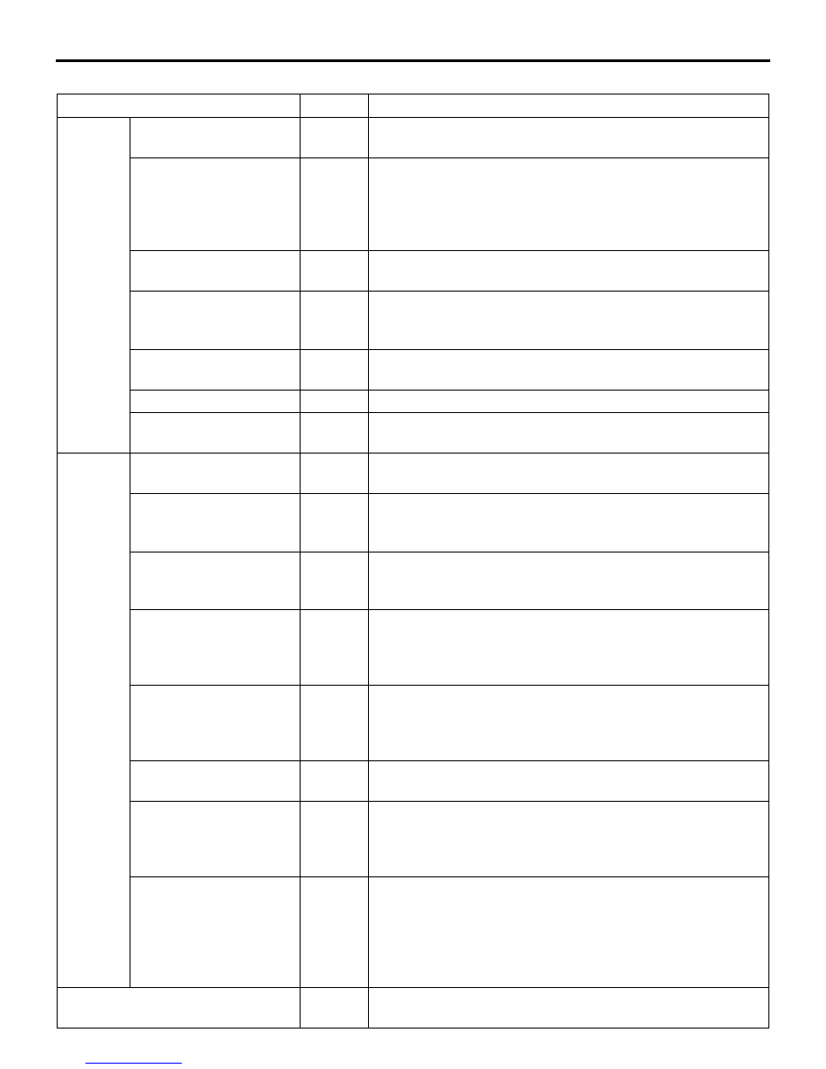
Name of part

Number Functional description

Sensor

Wheel speed sensor

1

Outputs the frequency signal in proportion to the rotation 
speed of each wheel to ASC-ECU.

Magnetic encoder for 
wheel speed detection

2

The wheel speed sensor is a pulse generator. When the 
magnetic encoder for wheel speed detection (a plate on 
which north and south pole sides of the magnets are 
arranged alternately) rotates, it outputs frequency pulse 
signal in proportion to each wheel speed.

Stop lamp switch

3

Outputs the signal indicating whether the brake pedal is 
depressed or not to ASC-ECU.

G & yaw rate sensor

4

Is integrated in the ASC-ECU, detects the yaw rate and 
longitudinal and lateral acceleration of a vehicle, and sends 
a signal to the ASC-ECU.

Steering wheel sensor

5

Detects the steering angle of the steering wheel, and 
outputs signal to ASC-ECU via the CAN bus line.

ASC OFF switch

6

Outputs the ON/OFF signal for ASC to ASC-ECU.

Brake fluid pressure 
sensor

7

Integrated into the hydraulic unit, and outputs the signal for 
the brake fluid pressure in the master cylinder to ASC-ECU.

Actuator

Hydraulic unit

8

Drives the solenoid valve using the signal from ASC-ECU, 
and controls the brake fluid pressure for each wheel.

ABS warning lamp

9

Informs the driver of the system status by illuminating, 
flashing, or turning off the ABS warning lamp according to 
the signal from ASC-ECU.

ABS warning display

10

Informs the driver of the system status by illuminating or 
turning off the ABS warning display according to the signal 
from ASC-ECU.

Brake warning lamp

11

Used as the brake warning lamp for the parking brake, 
brake fluid level, and EBD control. Informs the driver of the 
system status by illuminating or turning off the brake 
warning lamp according to the signal from ASC-ECU.

Brake warning display

12

Used as the brake warning display for the brake fluid level, 
and EBD control. Informs the driver of the system status by 
illuminating or turning off the brake warning display 
according to the signal from ASC-ECU.

ASC operation lamp

13

Informs the driver of the system status by flashing when the 
system operates according to the signal from ASC-ECU.

ASC OFF lamp

14

Informs the driver of the system shutdown by illuminating by 
the signal from ASC-ECU. Informs the driver that the brake 
system overheats and the brake TCL stops by flashing the 
ASC OFF lamp for the duration of approximately 2 Hz.

ASC warning display 
and lamp

15

TCL function and stability control function, HSA function use 
the same display and lamp. Depending on the signal from 
ASC-ECU, the ASC warning display and lamp informs the 
driver of the system status by illuminating when the system 
has malfunction (When the ASC warning display and lamp 
is illuminated, the HSA function does not operate).

Diagnosis connector

16

Sets the diagnosis code and establishes the communication 
with M.U.T.-III.

Downloaded from 

www.Manualslib.com


manuals search engine


ACTIVE STABILITY CONTROL SYSTEM (ASC)

ACTIVE STABILITY CONTROL SYSTEM (ASC)

35C-5

NOTE: 

.

*

: 4WD

Engine-ECU

17

Controls the engine output based on the signal from 
ASC-ECU.

CVT-ECU

18

CVT-ECU performs integrated control with ASC-ECU.
Output the gear position to ASC-ECU.

4WD-ECU

*

19

*

Outputs the drive status to ASC-ECU.
4WD-ECU performs integrated control with ASC-ECU.

ASC control unit (ASC-ECU)

20

Controls the actuators (hydraulic unit) based on the signals 
sent from sensors.

Controls the self-diagnostic function and fail-safe function.

Controls diagnostic function (Compatible with M.U.T.-III).

Name of part

Number Functional description

Downloaded from 

www.Manualslib.com


manuals search engine


ACTIVE STABILITY CONTROL SYSTEM (ASC)

ACTIVE STABILITY CONTROL SYSTEM (ASC)

35C-6

SCHEMATIC DIAGRAM

NOTE: 

.

Dashed lines indicate the CAN bus line.

*1

: 4WD

*2

: Vehicles with ACC/FCM

ACC02099

· 

Engine-ECU

· 

CVT-ECU

· 

4WD-ECU*1

· 

ACC/FCM-ECU*2

· 

Steering wheel sensor

· 

Stop lamp switch

· 

ASC OFF switch

· 

Engine-ECU

· 

CVT-ECU

· 

4WD-ECU*1

· 

ACC/FCM-ECU*2

Diagnosis 
connector

Combination meter and multi 
information display
· ABS warning lamp and display
· Brake warning lamp and display
· ASC operation lamp
· ASC OFF lamp
· ASC warning display and lamp

Parking brake
switch

FR suction valve

FL suction valve

FL cut valve

FR cut valve

FR solenoid valve (OUT)

FR solenoid valve (IN)

FL solenoid valve (OUT)

FL solenoid valve (IN)

RR solenoid valve (OUT)

RR solenoid valve (IN)

RL solenoid valve (OUT)

RL solenoid valve (IN)

G and yaw rate 
sensor

ASC-ECU

Wheel speed sensor (FL)

Wheel speed sensor (RL)

Wheel speed sensor (RR)

Wheel speed sensor (FR)

Master cylinder pressure sensor

ASC-ECU power supply

AB

Rear-left wheel (RL)

Wheel 
speed 
sensor 
(FL)

Front-left wheel (FL)

Wheel 
speed 
sensor 
(RL)

ASC OFF switch

Hydraulic 
unit

Rear-right wheel (RR)

Wheel 
speed 
sensor 
(RR)

Stop lamp switch

Stop lamp

Steering wheel sensor

Wheel 
speed 
sensor 
(FR)

Front-right wheel (FR)

ETACS-ECU

Stop lamp drive*2

Stop lamp monitor*2

Downloaded from 

www.Manualslib.com


manuals search engine


ACTIVE STABILITY CONTROL SYSTEM (ASC)

ACTIVE STABILITY CONTROL SYSTEM (ASC)

35C-7

ASC ELECTRICAL DIAGRAM

ACC02101

ASC-ECU 
power supply

ON

OFF

Stop 
lamp
switch

Field Effect Transistor

No.14
15A

ON

OFF

ASC OFF
switch

Steering 
wheel
sensor

Diagnosis 
connector

4WD-ECU
<4WD>

<Vehicles with ACC/FCM>

Engine-ECU

CVT-ECU

No.11
10A

ETACS-
ECU

Fusible link No.2

Interface
circuit

CAN drive
circuit

ON

OFF

IG1
relay

No.15
10A

Ignition switch (IG1) or
OSS-ECU (IG1)

G and yaw
rate sensor

Solenoid valve

Hydraulic unit

AB

ASC-ECU

Parking 
brake 
switch

ON

OFF

CPU

CAN 
transceiver
circuit

LCD
(ABS, ASC OFF, 
ASC WARNING, BRAKE)

LED drive 

circuit

ABS

ASC

ASC
OFF

BRAKE

Combination meter

Rheostat

Interface
circuit

Interface
circuit

CAN drive
circuit

(LH)

(RH)

(LH)

(RH)

Motor power supply

Solenoid valve power supply

Front wheel speed sensor

Rear wheel speed sensor

Fusible link 
No.4

Downloaded from 

www.Manualslib.com


manuals search engine


Content   ..  161  162  163  164   ..