Mitsubishi Outlander (2013+). Manual - part 153


  Index      Mitsubishi     Mitsubishi Outlander - service repair manual 2013 year


Search            


Content   ..  151  152  153  154   ..


Mitsubishi Outlander (2013+). Manual - part 153


ELECTRONICALLY CONTROLLED 4WD

REAR AXLE

27-10

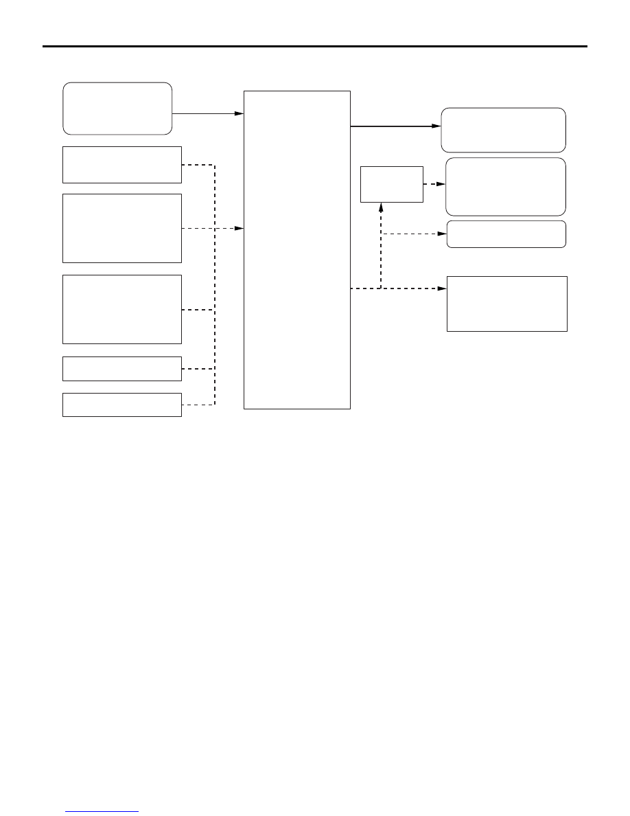
Control schematic diagram

ACC00456

4WD-ECU

4WD switch
(4WD ECO
 4WD AUTO
 4WD LOCK)

Engine-ECU
· Engine r/min
· Engine torque

ABS/ASC-ECU
· 4 wheels speed
· 4WD torque reduction
  requirement
· Yaw rate, longitudinal
  and lateral acceleration

Coupling torque

Combination meter
· Drive mode indicator 
  or display
· Fail information

Diagnosis output

ABS/ASC-ECU
· Drive mode
· Coupling torque

AC

CAN-C

CAN-C-Mid

CAN-C

ETACS-ECU
· Vehicle information
· Key position
· Battery voltage
· 

Ambient temperature

· Stop lamp switch

ETACS-ECU

NOTE:The dashed line indicates CAN communication
            lines (CAN-C, CAN-C-Mid).

CVT-ECU or A/T-ECU
· Gear position

Steering wheel sensor
· Steering angle

Downloaded from 

www.Manualslib.com


manuals search engine


ELECTRONICALLY CONTROLLED 4WD

REAR AXLE

27-11

Electronically controlled 4WD electric circuit diagram

4WD-ECU

M2270000500090

FUNCTION

The main functions of 4WD-ECU are as follows:

1. Communication function

• CAN communication with other ECUs (Engine 

ECU, CVT-ECU, A/T-ECU, ABS/ASC-ECU, 
steering wheel sensor, ETACS)

ACB05564

AD

Engine-ECU

Ignition switch(IG1)

Fusible link

Fusible link 

ABS/ASC
-ECU

Combination meter

4WD switch

Electronic control
coupling solenoid

NOTE:The dashed line indicates CAN communication lines.  

7.5 A

10 A

15 A

ETACS-ECU
(Fuse)

ETACS-ECU
(Fuse)

Diagnosis
connector

IG1
relay

4WD-ECU

ETACS-ECU

LCD

4WD ECO
4WD AUTO
4WD LOCK

CVT-ECU or
A/T-ECU

Steering 
wheel sensor

Downloaded from 

www.Manualslib.com


manuals search engine


ELECTRONICALLY CONTROLLED 4WD

REAR AXLE

27-12

• Communication with drive mode switch: The 

signal from the drive mode switch changes 
the drive mode.

• Combination meter display: Drive mode is dis-

played.

2. Coupling control function

• Current output: Differential control function of 

the electronic control coupling according to 
the vehicle conditions

3. ECU self-diagnosis function

• Initial check: ROM check, relay check, etc.

• Recording function of diagnosis codes and 

freeze frame data in case of failure

• System shutdown function after failure detec-

tion, "4WD-E" and "LOCK" indicator warning 
<standard meter> and message indication on 
display <high contrast meter>

• Normal control: Malfunction of CPU power 

supply, relay check, open or short circuit of 
the I/O signal, abnormal CAN communication

FAIL-SAFE FUNCTION

FAILURE DETECTION

4WD-ECU performs the following checks at a timing 
shown in the chart below. 4WD-ECU determines the 
malfunction occurred when the failure detection con-
ditions are met, and it sets the diagnosis code and 
executes the countermeasures for trouble. When the 
failure resume conditions are met, ECU determines 
the status is normal, and resumes the system.

NOTE: For the fail-safe specification, refer to Work-
shop Manual.

Start-up (Initial check just after the ignition 

switch is turned ON.)

1. CPU check

• Performs the ROM and RAM check.

2. Actuator check

• After CPU check has been completed, check 

the driving voltage with the actuator relay 
OFF.

Always (During ignition ON status other than ini-

tial check operation)

1. CPU check

• Performs CAN communication and interactive 

check between CPUs.

2. Power supply check

• Monitors the CPU supply voltage and checks 

if the voltage is within specifications.

3. Actuator check

• Checks if the actuator relay turns ON accord-

ing to the control.

• Compares the command current value from 

CPU with the monitored current and checks if 
they agree.

4. External wire connection check

• Checks if the input and output of each exter-

nal wire connection is open, shorted, or stuck.

DIAGNOSTIC FUNCTION

4WD-ECU has the following functions for easier sys-
tem checks. All of the following items can be diag-
nosed using the M.U.T.-III.

• Diagnosis code set

• Service data output

• Actuator test

• Freeze frame data output

DIAGNOSIS CODE SET

Using M.U.T.-III, the diagnosis code (information of 
failures generated in the electronically controlled 
4WD system) can be read. When a failure occurs, 
4WD-ECU sets the diagnosis code for that failure in 
the nonvolatile memory (EEPROM*), so the recorded 
information will not be erased even if the battery is 
disconnected.

NOTE: 

.

*EEPROM (Electrical Erasable & Programmable 
ROM): Special type of memory that can be pro-
grammed or erased electrically

For the diagnosis code output items of the elec-
tronically controlled 4WD, refer to Workshop 
Manual.

SERVICE DATA OUTPUT

Using M.U.T.-III, the data (input data from each ECU 
and switch) used for control by the electronically con-
trolled 4WD system can be read.

NOTE: For each service data item, refer to Work-
shop Manual.

ACTUATOR TEST

M.U.T.-III can forcibly drive the actuators (electronic 
control coupling solenoid and drive mode indicator) 
controlled by the electronically controlled 4WD sys-
tem.

NOTE: For the actuator test specification, refer to 
Workshop Manual.

FREEZE FRAME DATA OUTPUT

M.U.T.-III can read the freeze frame data (driving 
conditions when the failure occurs) set when the 
diagnosis code is detected.

NOTE: For freeze frame data items, refer to Work-
shop Manual.

Downloaded from 

www.Manualslib.com


manuals search engine


ELECTRONICALLY CONTROLLED 4WD

REAR AXLE

27-13

4WD SWITCH

M2270001300022

The 4WD switch has been installed on the floor con-
sole. When the 4WD switch is operated with the igni-
tion switch ON, the drive mode can alternate 4WD 
ECO, 4WD AUTO or 4WD LOCK.

If the ECO switch is turned on during 4WD AUTO 
mode, the drive mode will switch into 4WD ECO to 
reduce fuel consumption. When the ECO switch is 
turned off during 4WD ECO mode, the drive mode 
will return to 4WD AUTO. During 4WD LOCK, the 
system does not switch the drive mode regardless of 
the ECO switch position.

ELECTRONIC CONTROL COUPLING

M2270000700072

FEATURES

The electronic control coupling realizes the highly reliable 4WD system with lighter weight and simpler con-
struction.

CONSTRUCTION

The electronic control coupling is comprised of the 
front housing, main clutch, main cam, ball, pilot cam, 
armature, pilot clutch, rear housing, magnetic coil, 
and shaft.

• The front housing is joined to the propeller shaft 

and rotates along with the shaft.

• The main clutch and pilot clutch are assembled to 

the front housing on the outer side and to the 
shaft on the inner side (The pilot clutch is 
installed via the pilot cam).

• The shaft is engaged via serrations with the drive 

pinion of the rear differential.

AC505099AC

Main clutch

Pilot clutch

Armature

Ball

Main cam

Magnet coil

Front housing

Rear housing

Rear differential

Shaft

Drive pinion

Pilot cam

Downloaded from 

www.Manualslib.com


manuals search engine


Content   ..  151  152  153  154   ..