Mitsubishi Outlander (2013+). Manual - part 154
ELECTRONICALLY CONTROLLED 4WD
REAR AXLE
27-14
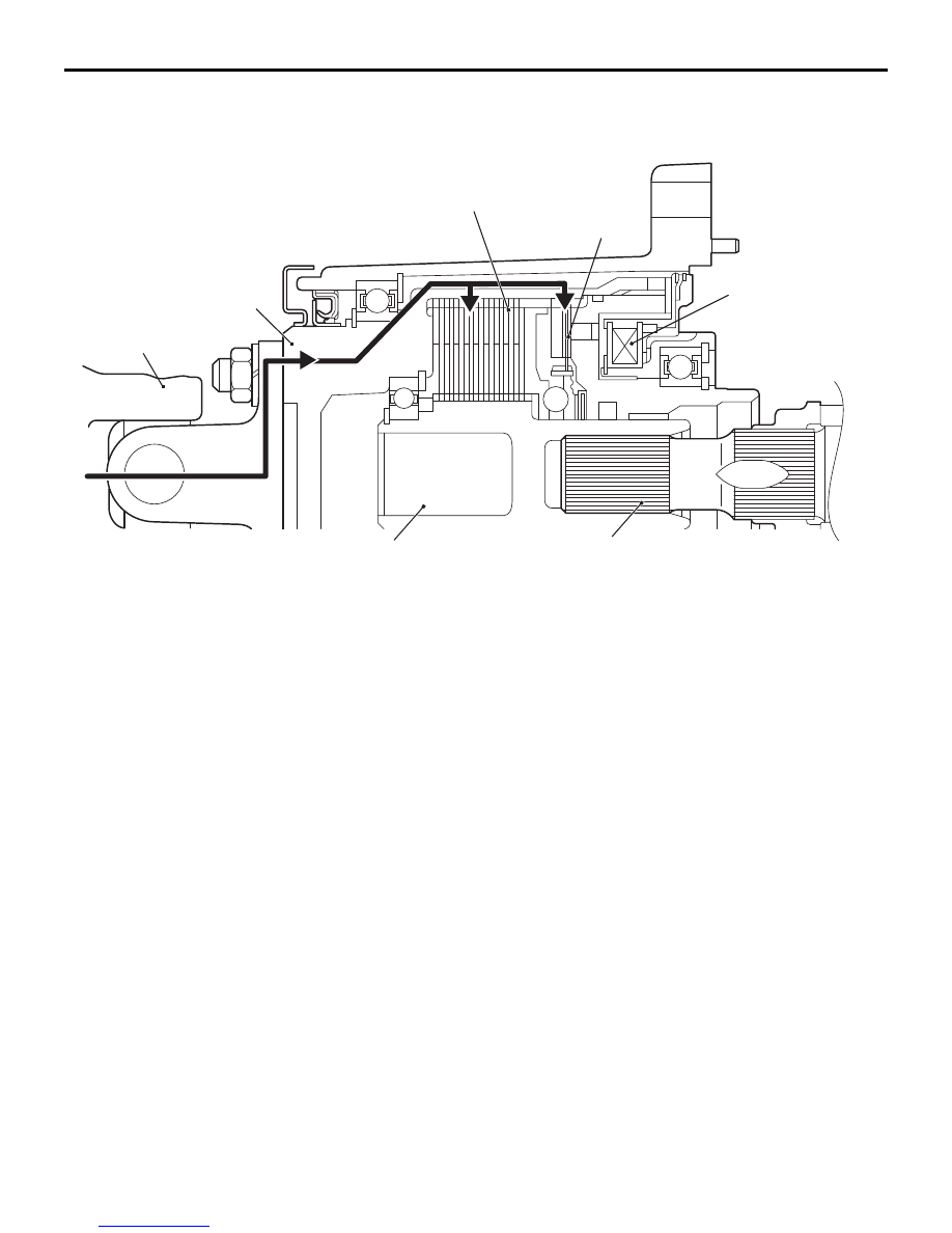
OPERATION
Coupling stops (2WD: Magnetic coil de-energized.)
The drive force from the transfer is transmitted to the
front housing connected to the propeller shaft. The
drive force is also transferred to the pilot clutch and
the outer side of the main clutch assembled to the
front housing. Because the pilot clutch and the main
clutch are not engaged with the magnetic coil
de-energized, the drive force is not transferred to the
shaft and the drive pinion of the rear differential.
AC505106AE
Main clutch
Shaft
Front housing
Propeller shaft
Pilot clutch
Drive pinion
(Rear differential)
Magnet coil
manuals search engine