Mitsubishi Outlander (2013+). Manual - part 64


  Index      Mitsubishi     Mitsubishi Outlander - service repair manual 2013 year


Search            


Content   ..  62  63  64  65   ..


Mitsubishi Outlander (2013+). Manual - part 64


CONSTRUCTION DIAGRAM

ACTIVE STABILITY CONTROL SYSTEM (ASC)

35C-9

ASC OPERATION DISPLAY AND LAMP, 
ASC WARNING DISPLAY AND LAMP, ASC 
OFF lamp

The ASC system illuminates or flashes the ASC 
operation display and lamp, ASC warning display 
and lamp or ASC OFF lamp in the following opera-
tion patterns, and informs the driver of the ASC sys-
tem status.

ASC operation display and lamp

• Flashes in 2 Hz (display)/4 Hz (lamp) during the 

ASC control.

ASC warning display and lamp

• Turns ON when the system malfunction occurs.

ASC OFF lamp

• ASC-ECU detects the overheat of the brake 

pads. When the brake TCL control is prohibited, 
the ASC OFF lamp flashes in approximately 2 
Hz.

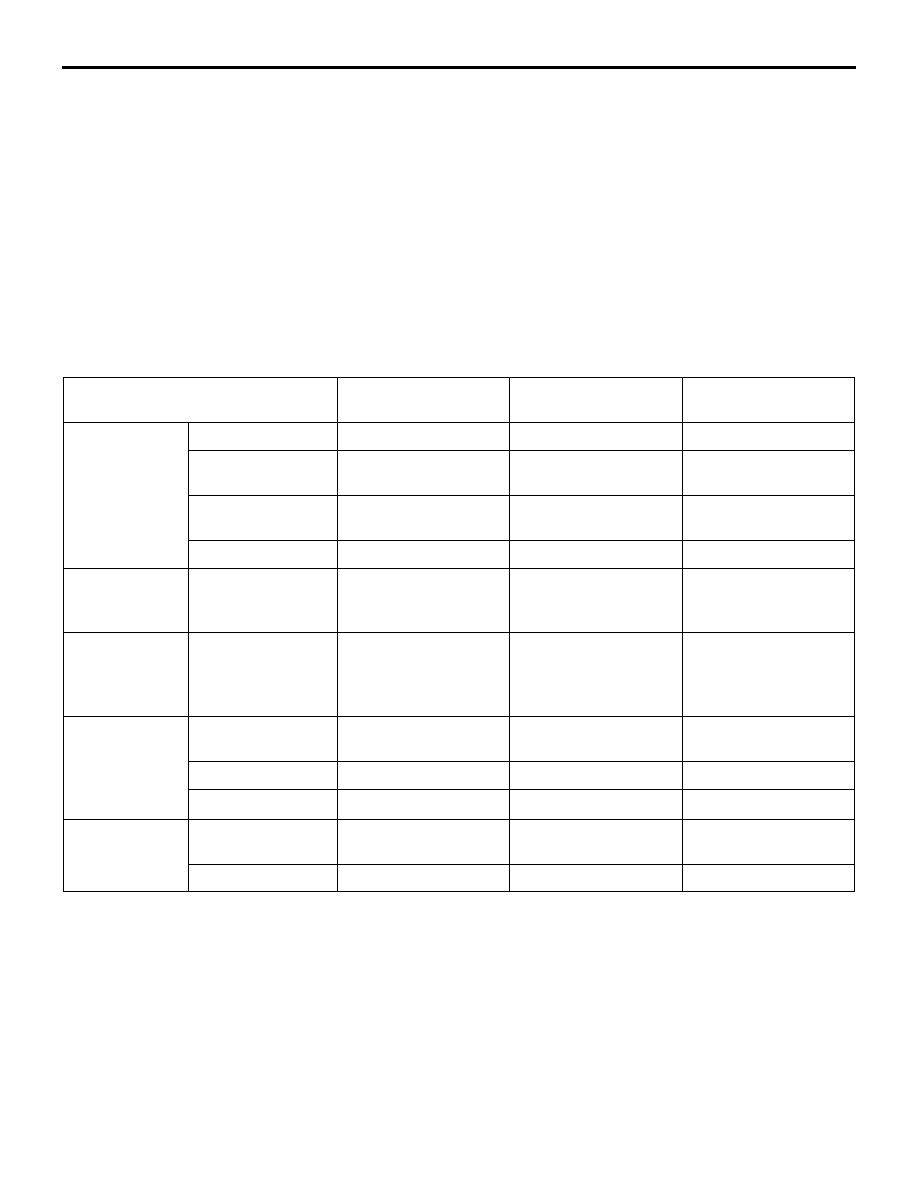
ASC operation display and lamp, ASC warning display and lamp, ASC OFF lamp illumination and 
flashing patterns

NOTE: 

*

 Illuminates if the TCL function or stability control function is defective when the HSA function is 

defective. (HSA control prohibited)

ASC-ECU

M2357000100515

This ECU incorporates the ABS function, EBD func-
tion, HSA function, stability control function and TCL 
function, brake assist control.

The hydraulic units of the ASC and TCL systems 
employ the automatic pressurisation function. These 
systems also incorporates G and yaw rate sensor 
(integrated with ASC-ECU), steering wheel sensor, 
and master cylinder pressure sensor (integrated with 
hydraulic unit).

State

ASC operation 
display and lamp

ASC warning display 
and lamp

ASC OFF lamp

Normal

Normal

Stability control 
operated

Flashing (display: 2 
Hz, lamp: 4 Hz)

TCL operated

Flashing (display: 2 
Hz, lamp: 4 Hz)

HSA operated

ASC is disabled 
by ASC OFF 
switch

ASC disabled

Illuminates

When the brake 
pad 
temperature is 
high

ASC-ECU informs 
the driver that the 
brake TCL does 
not function.

Flashing (2 Hz)

Abnormal

Stability control 
malfunction

Illuminates

Illuminates

TCL malfunction

Illuminates

Illuminates

HSA malfunction

Illuminates

*

M.U.T.-III 
connection

Actuator not 
operated

Actuator operated

Illuminates

Illuminates

CONSTRUCTION DIAGRAM

ACTIVE STABILITY CONTROL SYSTEM (ASC)

35C-10

STABILITY CONTROL DESCRIPTION

ASC-ECU detects vehicle movement based on infor-
mation from various sensors and calculates a model 
of ideal vehicle movement. ASC-ECU compares the 
actual vehicle movement with the ideal vehicle 
model, and manages the brake of the specific wheel 
so that the actual vehicle movement gets close to the 
ideal vehicle mode. It also controls the understeer or 
oversteer condition by creating the yaw moment in 
the vehicle.

Example of Stability Control function

The Stability Control manages the vehicle attitude by 
creating a yaw moment from altering the balance 
between the cornering force and each wheel's brak-
ing mechanism.

Example of the effect of control

AC604152AB

<Generation of counter-rotating force>

<Generation of rotating force>

Large braking 
force

Large braking 
force

AC604154AB

Suppression of rear wheel side slip

Suppression of front wheel side slip

Prevents spinning 
caused by 
rear wheel side slip

Prevents the vehicle 
from getting out of course 
by front wheel side slip

CONSTRUCTION DIAGRAM

ACTIVE STABILITY CONTROL SYSTEM (ASC)

35C-11

For example, on a slippery surface, if the vehicle 
tends to be under-steered contrary to the driver’s 
intention, a yaw moment (a rotational moment) is 
created to restrain the under-steering by increasing 
the rear-inside braking force. On the other hand, 
when the vehicle tends to be oversteered, a yaw 

moment (a restorative moment) is created to restrain 
the oversteering by increasing the front-outside 
wheel braking force. Furthermore, when it is deter-
mined that the vehicle is over-speeding, safe and 
stable cornering is enabled by deceleration from 
reducing the engine output.

Joint control

ASC-ECU transmits data necessary for control of 
ABS and TCL, performing joint control.

Example of TCL function

2WD

4WD

Control system

Control content

ABS

Even during ABS operation, ABS performance is improved from the joint 
operation of the stability control.

TCL

During acceleration, engine output is governed through joint operation with 
stability control.

AC705575AB

Slipping wheel

Brake force

Slippery surface 

Direction of
driving

Driving
force

AC706148

Brake force

Driving 
force

Direction of 
driving

Slipping wheel

Slippery surface

AB

Slipping wheel

Slippery surface

Driving 
force

Brake force

CONSTRUCTION DIAGRAM

ACTIVE STABILITY CONTROL SYSTEM (ASC)

35C-12

When the driving wheels slip on the slippery road 
surface, TCL applies the brake automatically, sends 
the signal requesting engine speed reduction to the 
engine-ECU, and prevents the loss of the driving 
force resulting from the slippage of the driving wheel.

Hill START ASSIST (HSA) FUNCTION

System configuration

When the vehicle has completely stopped on a steep 
uphill by the service brake, ASC-ECU judges 
whether or not start the HSA function control in 
accordance with the signals (ETACS-ECU, 
CVT-ECU, G & yaw rate sensor, brake fluid pressure 
sensor, engine-ECU, wheel speed sensor).

ACB06022

gear position information

CVT-ECU

Parking brake switch

ETACS-ECU

engine related information

Engine-ECU

: Hardwire-line
: CAN line
: Brake-line

Wheel speed sensor

Combination meter

FL

FR

RL

RR

AB

Hydraulic unit

ASC-ECU

Master cylinder 
pressure sensor

G and yaw rate 
sensor

HSA control

Brake fluid 
currently 
supplied to each
wheel cylinder 
is controlled.


Content   ..  62  63  64  65   ..