Mitsubishi Outlander (2013+). Manual - part 45
GENERAL INFORMATION
ENGINE COOLING
14-2
GENERAL INFORMATION
M2140000101567
For the cooling method, a forced water-cooling circu-
lation system is adopted and it has the following
characteristics:
• To reduce the coolant temperature variation, the
inlet control system which arranges the thermo-
stat at the inlet side of the coolant flowing from
the radiator to the engine is adopted.
• A down-flow radiator has been adopted in order
to reduce the number of parts and improve serv-
iceability.
• A ring fan has been adopted in order to reduce
noise.
• A radiator condenser tank is assembled into the
fan shroud in order to reduce the number of parts
and improve serviceability.
SPECIFICATIONS
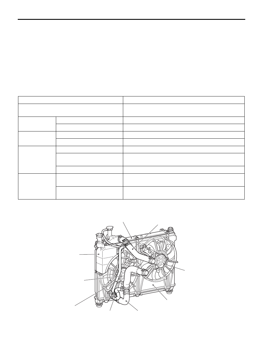
CONSTRUCTION DIAGRAM
Item
4B1
Cooling method
Water-cooled pressurised, forced circulation with
electrical fan
Water pump
Type
Centrifugal impeller
Drive method
Drive belt
Thermostat
Type
Wax pellet with jiggle valve
Valve open temperature
°C
82
± 1.5
Radiator
Type
Pressurised corrugate type
Core size (width
× height ×
thickness) mm
687.4
× 400 × 16
Performance kJ/h
201,800
Engine coolant
Specified coolant
DIA QUEEN SUPER LONG LIFE COOLANT or
equivalent
Quantity (including 0.65 L in
the radiator condenser tank) L
Approximately 7.5
ACB05950
Radiator lower hose
assembly
Radiator condenser tank
Radiator upper hose assembly
Radiator assembly
Radiator fan motor
Condenser fan motor
Fan shroud
CVT fluid cooler
feed hose
AB
CVT fluid cooler
return hose