Mitsubishi Outlander (2003+). Manual - part 547
SPECIAL TOOL
AUTOMATIC AIR CONDITIONER
55B-3
MB991955
A: MB991824
B: MB991827
C: MB991910
D: MB991911
E: MB991825
F: MB991826
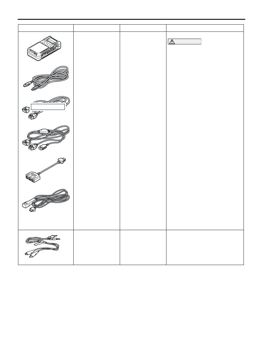
MUT-III
sub-assembly
A: Vehicle
Communication
Interface (V. C. I.)
B: MUT-III USB
cable
C: MUT-III main
harness A (Vehicles
with CAN
communication
system)
D: MUT-III main
harness B (Vehicles
without CAN
communication
system)
E: MUT-III
measurement
adapter
F: MUT-III trigger
harness
Automatic A/C check
CAUTION
MUT-III main harness B
(MB991911) should be used.
MUT-III main harness A should
not be used for this vehicle.
MB991529
Diagnosis code
check harness
Automatic A/C check with a
voltmeter
Tool
Number
Name
Use
MB991910
MB991826
MB991955
MB991911
MB991824
MB991827
MB991825
A
B
C
D
E
F
DO NOT USED
MB991529