Mitsubishi Outlander (2003+). Manual - part 543
BLOWERMOTOR, RESISTOR AND OUTSIDE/INSIDE AIR SELECTION DAMPER CONTROL MOTOR
HEATER, AIR CONDITIONER AND VENTILATION
55A-67
INSPECTION
M1551006300264
RESISTER CHECK
Use an ohmmeter to measure the resistance
between the terminals. Check that the measured
value is at the standard value.
Standard value:
BLOWER FAN AND MOTOR CHECK
When battery voltage is applied between the
terminals, check that the motor operates. Also, check
that there is no abnormal noise.
OUTSIDE/INSIDE AIR SELECTION DAMPER
CONTROL MOTOR CHECK
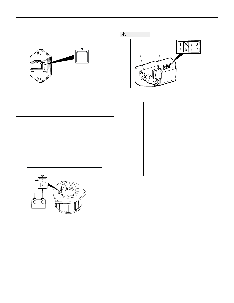
CAUTION
Cut off the battery voltage when the damper is in
the inside/outside air position.
Measurement terminal
Standard value (
Ω
)
Between terminals 2 and 4
(LO)
2.54
Between terminals 1 and 2
(ML)
1.24
Between terminals 2 and 3
(MH)
0.6
AC103700
1
3 4
2
AC100626 AB
Lever
position
Battery connection Lever
operation
At the
inside
position
•
Connect terminal
7 to the positive
battery terminal
•
Connect terminal
4 to the negative
battery terminal
The lever
moves from the
inside position
to the outside
position
At the
outside
position
•
Connect terminal
7 to the positive
battery terminal
•
Connect terminal
6 to the negative
battery terminal
The lever
moves from the
outside position
to the inside
position
AC201501
INSIDE AIR
OUTSIDE AIR
AB