Mitsubishi Outlander (2003+). Manual - part 510


  Index      Mitsubishi     Mitsubishi Outlander - service repair manual 2003 year


Search            


Content   ..  508  509  510  511   ..


Mitsubishi Outlander (2003+). Manual - part 510


INPUT SIGNAL PROCEDURES

SMART WIRING SYSTEM (SWS) NOT USING SWS MONITOR

54B-329

Prior to the wiring harness inspection, check 
intermediate connectors C-118 <L.H. drive 
vehicles>, E-12 <L.H. drive vehicles>, C-15 <R.H. 
drive vehicles>, E-32 <R.H. drive vehicles> and joint 
connector C-02, and repair if necessary.

Check the communication lines for open circuit.

Q: Is the check result normal?

YES : 

Go to Step 4.

NO : 

Repair the wiring harness.

Step 4. Replace the power window main switch, 
and then retest the system.

Replace the power window main switch, and check 
that the power window main switch signal is 
received.
(1) Replace the power window main switch.
(2) Check that the power window main switch signal 

is received.

Q: Is the check result normal?

YES : 

The procedure is complete.

NO : 

Replace the ETACS-ECU.

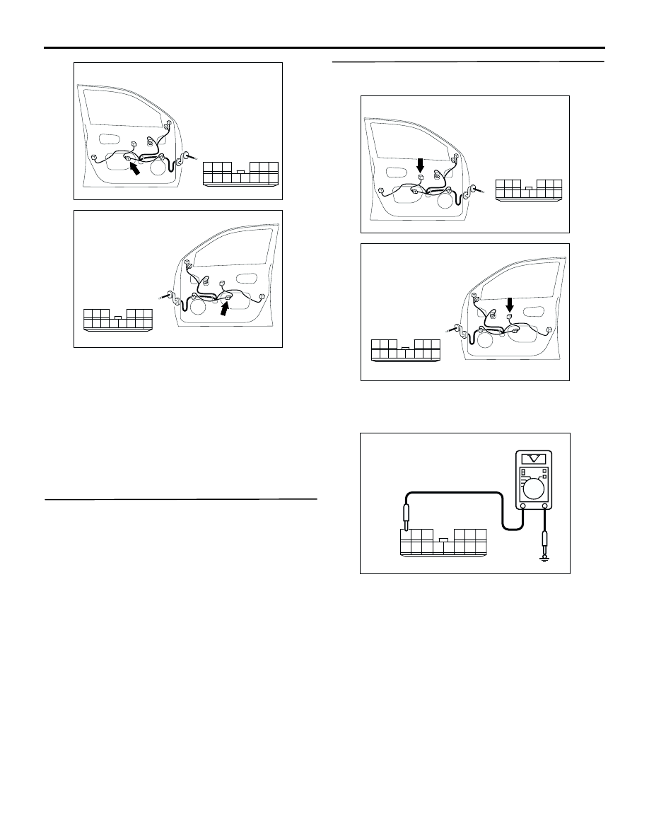
Step 5. Measure the voltage at the E-05 power 
window main switch connector.

(1) Remove the power window main switch, and 

measure at the wiring harness side.

(2) Ignition switch: ON position

(3) Voltage between E-05 power window main switch 

connector terminal No.6 and body earth

OK: System voltage

Q: Is the check result normal?

YES : 

Go to Step 8.

NO : 

Go to Step 6.

AC308791

10

1

6

14

5

12

13

4

11

7

2

3

8

9

AD

Connector: E-12 
<LHD>

Harness side

AC308797

10

1

6

14

5

12

13

4

11

7

2

3

8

9

AD

Connector: E-32 
<RHD>

Harness side

AC308791

10

1

6

14

5

12

13

4

11

7

2

3

8

9

AC

Connector: E-05

Harness side

<LHD>

AC308797

10

1

6

14

5

12

13

4

11

7

2

3

8

9

AC

Connector: E-05

Harness side

<RHD>

AC301541BH

Connector E-05
(Harness side)

10

1

6

14

5

12

13

4

11

7

2

3

8

9

INPUT SIGNAL PROCEDURES

SMART WIRING SYSTEM (SWS) NOT USING SWS MONITOR

54B-330

Step 6. Connector check: C-208 power window 
relay connector

Q: Is the check result normal?

YES : 

Go to Step 7.

NO : 

Repair the defective connector.

Step 7. Check the wiring harness between C-208 
power window relay connector terminal No.4 and 
E-05 power window main switch connector 
terminal No.6.

AC308720

Connector: C-208

AG

3

4

5

1

2

Junction block (Front view)

Junction block side

<LHD>

AC308772

Connector: C-208

AF

3

4

5

1

2

Junction block (Front view)

Junction block side

<RHD>

AC308720

Connector: C-208

AG

3

4

5

1

2

Junction block (Front view)

Junction block side

<LHD>

AC308772

Connector: C-208

AF

3

4

5

1

2

Junction block (Front view)

Junction block side

<RHD>

AC308791

10

1

6

14

5

12

13

4

11

7

2

3

8

9

AC

Connector: E-05

Harness side

<LHD>

AC308797

10

1

6

14

5

12

13

4

11

7

2

3

8

9

AC

Connector: E-05

Harness side

<RHD>

INPUT SIGNAL PROCEDURES

SMART WIRING SYSTEM (SWS) NOT USING SWS MONITOR

54B-331

NOTE: 

Prior to the wiring harness inspection, check 
intermediate connectors C-118 <L.H. drive 
vehicles>, E-12 <L.H. drive vehicles>, C-15 <R.H. 
drive vehicles>, E-32 <R.H. drive vehicles> and 
junction block connector C-203, and repair if 
necessary.

Check the power supply line for open circuit.

Q: Is the check result normal?

YES : 

The trouble can be an intermittent 

malfunction (Refer to GROUP 00 

 How to 

Cope with Intermittent Malfunction 

P.00-6

).

NO : 

Repair the wiring harness.

AC308769

AI

Connector: C-15 <RHD>

AC308716

AH

Connector: C-118 
<LHD>

32

22

11

27

16

5

24

13

2

12

23

1

15

14

26

25

3 4

29

19

8

18

17

28

6 7

21

20

30 31

9 10

AC308720AD

Connector: C-203

Jnction block (Front view)

Harness side

<LHD>

AC308772 AE

Connector: C-203

Jnction block (Front view)

Harness side

<RHD>

AC308791

10

1

6

14

5

12

13

4

11

7

2

3

8

9

AD

Connector: E-12 
<LHD>

Harness side

AC308797

10

1

6

14

5

12

13

4

11

7

2

3

8

9

AD

Connector: E-32 
<RHD>

Harness side

INPUT SIGNAL PROCEDURES

SMART WIRING SYSTEM (SWS) NOT USING SWS MONITOR

54B-332

Step 8. Measure the resistance at the E-05 power 
window main switch connector.

(1) Remove the power window main switch, and 

measure at the wiring harness side.

(2) Resistance between E-05 power window main 

switch connector terminal No.2 and body earth

OK: 2

 or less

Q: Is the check result normal?

YES : 

Go to Step 10.

NO : 

Go to Step 9.

Step 9. Check the wiring harness between E-05 
power window main switch connector terminal 
No.2 and body earth.

AC308791

10

1

6

14

5

12

13

4

11

7

2

3

8

9

AC

Connector: E-05

Harness side

<LHD>

AC308797

10

1

6

14

5

12

13

4

11

7

2

3

8

9

AC

Connector: E-05

Harness side

<RHD>

AC301541BI

Connector E-05
(Harness side)

10

1

6

14

5

12

13

4

11

7

2

3

8

9

AC308791

10

1

6

14

5

12

13

4

11

7

2

3

8

9

AC

Connector: E-05

Harness side

<LHD>

AC308797

10

1

6

14

5

12

13

4

11

7

2

3

8

9

AC

Connector: E-05

Harness side

<RHD>


Content   ..  508  509  510  511   ..