Mitsubishi Outlander (2003+). Manual - part 491


  Index      Mitsubishi     Mitsubishi Outlander - service repair manual 2003 year


Search            


Content   ..  489  490  491  492   ..


Mitsubishi Outlander (2003+). Manual - part 491


SYMPTOM PROCEDURES

SMART WIRING SYSTEM (SWS) NOT USING SWS MONITOR

54B-253

NOTE: 

Prior to the wiring harness inspection, check 
intermediate connector C-14 <side RH>, and repair if 
necessary.

Check the earth wires for open circuit.

Q: Is the check result normal?

YES : 

The trouble can be an intermittent 

malfunction (Refer to GROUP 00 

 How to 

Cope with Intermittent Malfunction 

P.00-6

).

NO : 

Repair the wiring harness.

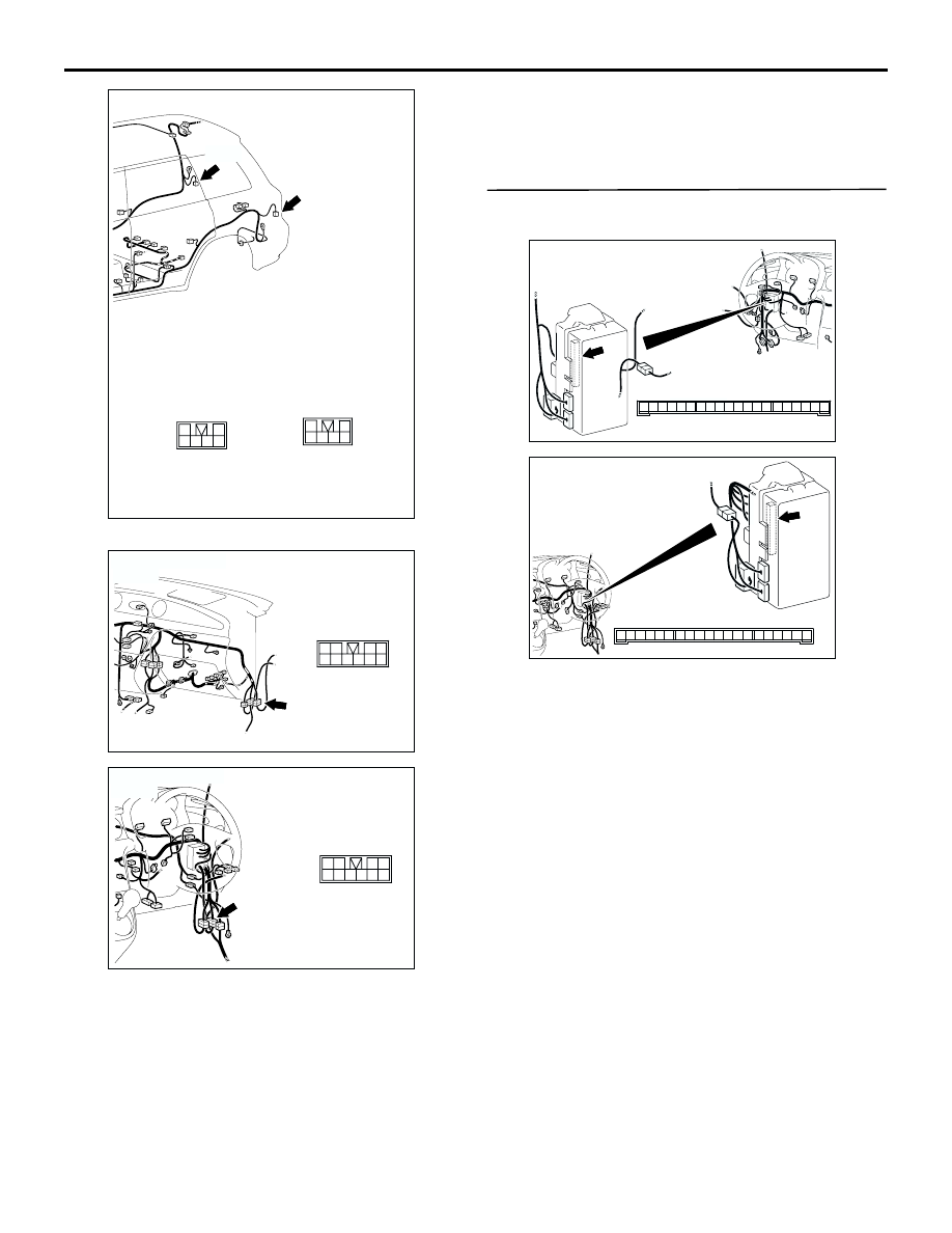
Step 5. Connector check: C-217 ETACS-ECU 
connector

Q: Is the check result normal?

YES : 

Go to Step 6.

NO : 

Repair the defective connector.

AC308788

Connectors: D-14, D-19

1
3

4

5

2
6

AD

D-14

1
3

4

5

2
6

D-19

Harness side

D-19

D-14

<RHD>

AC308718

Connector: C-14

AI

9

3

2

1
5 6 7 8

4

10

<LHD>

AC308769

Connector: C-14

AM

9

3

2

1
5 6 7 8

4

10

<RHD>

AC308722

Connector: C-217

Junction block (Rear view)

Junction block side

AD

3

1

2

14

4

5

7 6

8

1110 9

1312

17

15

16

18

19

20

<LHD>

AC308776

Connector: C-217

Junction block (Rear view)

Junction block side

AC

3

1

2

14

4

5

7 6

8

1110 9

1312

17

15

16

18

19

20

<RHD>

SYMPTOM PROCEDURES

SMART WIRING SYSTEM (SWS) NOT USING SWS MONITOR

54B-254

Step 6. Check the wiring harness from the A-29 
<front RH> or A-16 <front LH> front turn-signal 
lamp connector terminal No.3, the A-01 <side 
RH> or A-04 <side LH> side turn-signal lamp 
connector terminal No.2, the D-14 <rear RH> or 
D-19 <rear LH> rear combination lamp connector 
terminal No.6, the C-05 <turn-signal indicator 
lamp RH> combination meter connector terminal 
No.10 or C-04 <turn-signal indicator lamp LH> 
combination lamp connector terminal No.31 to 
C-217 ETACS-ECU connector terminal No.9 <RH> 
or 14 <LH>.

AC308678

A-29(B)

2 1

A-29

5

6

3 2

4

1

A-01

A-01(GR)

AB

Connectors: A-01, A-29

Harness side

<LHD>

AC308685

A-29(B)

2 1

A-29

5

6

3 2

4

1

A-01

A-01(GR)

AB

Connectors: A-01, A-29

Harness side

<RHD>

AC308680

A-16(B)

AB

2 1

A-16

5

6

3 2

4

1

A-04

A-04(GR)

Connectors: A-04, A-16

Harness side

<LHD>

SYMPTOM PROCEDURES

SMART WIRING SYSTEM (SWS) NOT USING SWS MONITOR

54B-255

AC308687

A-16(B)

AB

2 1

A-16

5

6

3 2

4

1

A-04

A-04(GR)

Connectors: A-04, A-16

Harness side

<RHD>

AC308717

Connectors: C-04, C-05, C-116

AF

C-04

C-05

G

G

22

11

5

16

19

20

21

17

18

8

10 9

7 6

13

1514

12

2

4 3

1

G

G

52

41

35
46

49

50

51

47

48

38

4039

3736

43

4544

42

32

3433

31

C-04

C-05(L)

9

21

33

35

24

12

3 4

7

8

5 6

39

28

41

30

18

4243

31

1920

32

40

29

1617

38

27

15

37

36

26

14

13

25

2

1

34

23

11

10

22

C-116

C-116

Harness side

<LHD>

AC308770

Connectors: C-04, C-05

AC

C-04

C-05

C-04

C-05(L)

Harness side

<RHD>

AC308735

AK

9

21

33

35

24

12

3 4

7

8

5 6

39

28

41

30

18

4243

31

1920

32

40

29

1617

38

27

15

37

36

26

14

13

25

2

1

34

23

11

10

22

C-116

C-116

Connectors; C-116
<RHD>

SYMPTOM PROCEDURES

SMART WIRING SYSTEM (SWS) NOT USING SWS MONITOR

54B-256

AC308784

Connectors: D-14, D-19

1
3

4

5

2
6

AD

D-14

1
3

4

5

2
6

D-19

Harness side

D-19

D-14

<LHD>

AC308788

Connectors: D-14, D-19

1
3

4

5

2
6

AD

D-14

1
3

4

5

2
6

D-19

Harness side

D-19

D-14

<RHD>

AC308722

Connector: C-217

Junction block (Rear view)

Junction block side

AD

3

1

2

14

4

5

7 6

8

1110 9

1312

17

15

16

18

19

20

<LHD>

AC308776

Connector: C-217

Junction block (Rear view)

Junction block side

AC

3

1

2

14

4

5

7 6

8

1110 9

1312

17

15

16

18

19

20

<RHD>


Content   ..  489  490  491  492   ..