Mitsubishi Outlander (2003+). Manual - part 484


  Index      Mitsubishi     Mitsubishi Outlander - service repair manual 2003 year


Search            


Content   ..  482  483  484  485   ..


Mitsubishi Outlander (2003+). Manual - part 484


SYMPTOM PROCEDURES

SMART WIRING SYSTEM (SWS) NOT USING SWS MONITOR

54B-225

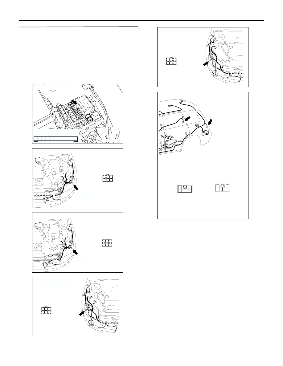
Step 6. Check the wiring harness from D-14 
<right tail lamp> or D-19 <left tail lamp> rear 
combination lamp connector terminal No.2, A-29 
<right position lamp> or A-16 <left position 
lamp> headlamp assembly connector terminal 
No.2, F-08 <right licence plate lamp> or F-10 <left 
licence plate lamp> licence plate lamp connector 
terminal No.2 to A-11X front-ECU connector 
terminal No.4.

AC301515 AD

Connector: A-11X

5

11

9

10

8 7 6

2

4 3

1

Relay box side

AC308679

5

6

3 2

4

1

A-16(B)

AC

Connector: A-16

Harness side

<LHD>

AC308686

5

6

3 2

4

1

A-16(B)

AC

Connector: A-16

Harness side

<RHD>

AC308677AC

A-29(B)

5

6

3 2

4

1

Connector: A-29

Harness side

<LHD>

AC308684

AC

A-29(B)

5

6

3 2

4

1

Connector: A-29

Harness side

<RHD>

AC308784

Connectors: D-14, D-19

1
3

4

5

2
6

AB

D-14

1
3

4

5

2
6

D-19

Harness side

D-19

D-14

<LHD>

SYMPTOM PROCEDURES

SMART WIRING SYSTEM (SWS) NOT USING SWS MONITOR

54B-226

NOTE: 

AC308788

Connectors: D-14, D-19

1
3

4

5

2
6

AC

D-14

1
3

4

5

2
6

D-19

Harness side

D-19

D-14

<RHD>

AC308809

Connectors: F-08, F-10

AD

F-08

F-08(GR)

Harness side

F-10(GR)

2 1

F-10

2 1

AC308717

AC

Connectors: C-01, C-116, C-117

38

1213

11

26

14

1

20

6

232425

37

31

36

30

10

9

2122

35

8

7

34

17

29

18 19

5

4

1516

33

28

32

27

3

2

C-117

C-117

9

21

33

35

24

12

3 4

7

8

5 6

39

28

41

30

18

4243

31

1920

32

40

29

1617

38

27

15

37

36

26

14

13

25

2

1

34

23

11

10

22

C-116

C-116

33

22

11

28

17

16

15

14

13

12

25

2324

2627

3

1 2

4 5

21

20

19

18

2930

32

31

7

6

8

10

9

C-01

C-01

<LHD>

AC308721

Connectors: C-202, C-209

AE

Junction block (Front view)

C-202

Harness side

C-202

10

1

6

14

5

12

13

4

11

7

2

3

8

9

C-209

7

15

5

6

1413

2

9

12

4 3

10

11

1

8

C-209

<LHD>

SYMPTOM PROCEDURES

SMART WIRING SYSTEM (SWS) NOT USING SWS MONITOR

54B-227

Prior to the wiring harness inspection, check joint 
connector C-01 <right tail lamp (L.H. drive 
vehicles)>, intermediate connector C-116 <tail lamp 
and licence plate lamp>, C-117 <left tail lamp and 
licence plate lamp>, D-31 <right tail lamp (L.H. drive 
vehicles)>, F-09 <licence plate lamp>, junction block 
connector C-202 <right tail lamp> and C-209 <right 
tail lamp (L.H. drive vehicles)> and C-221 <right tail 
lamp (R.H. drive vehicles)>, and repair if necessary.

Check the output lines for open circuit.

Q: Is the check result normal?

YES : 

Go to Step 7.

NO : 

Repair the wiring harness.

Step 7. Retest the system.

Check that the tail lamps, the position lamps and the 
licence plate lamps illuminate normally.

Q: Is the check result normal?

The lamps illuminate normally at both high and low 
beams. : 

The trouble can be an intermittent 

malfunction (Refer to GROUP 00 

 How to 

Cope with Intermittent Malfunction 

P.00-6

).

When the tail lamps do not illuminate : 

Replace 

the rear combination lamp socket assembly.

When the position lamps do not illuminate : 

Replace the position lamp socket.

When the licence plate lamps do not illuminate : 

Replace the licence plate lamp socket.

AC308773

Connectors: C-202, C-209

AF

Junction block (Front view)

C-202

Harness side

C-202

10

1

6

14

5

12

13

4

11

7

2

3

8

9

C-221

7

15

5

6

1413

2

9

12

4 3

10

11

1

8

C-221

<RHD>

AC308781

Connector: D-31

AC

11

1

4

3

10
16

13

12

5 6

2

14

8

15

9

7

<LHD>

SYMPTOM PROCEDURES

SMART WIRING SYSTEM (SWS) NOT USING SWS MONITOR

54B-228

INSPECTION PROCEDURE J-7: The headlamp(s) do not illuminate. <including high-beam indicator>

CAUTION

Whenever the ECU is replaced, ensure that the 
input and output signal circuits are normal.

COMBINATION 
METER

FRONT-ECU

HEADLAMP

(LH)

(RH)

HEADLAMP 
RELAY: HI

HEADLAMP 
RELAY: LO

Wire colour code
B : Black     LG : Light green     G : Green     L : Blue     W : White     Y : Yellow     SB : Sky blue
BR : Brown     O : Orange     GR : Gray     R : Red     P : Pink     V : Violet   

RELAY BOX

Headlamps (

High-Beam Indicator Lamp

) Circuit <LHD>


Content   ..  482  483  484  485   ..