Mitsubishi Outlander (2003+). Manual - part 440
SYMPTOM PROCEDURES
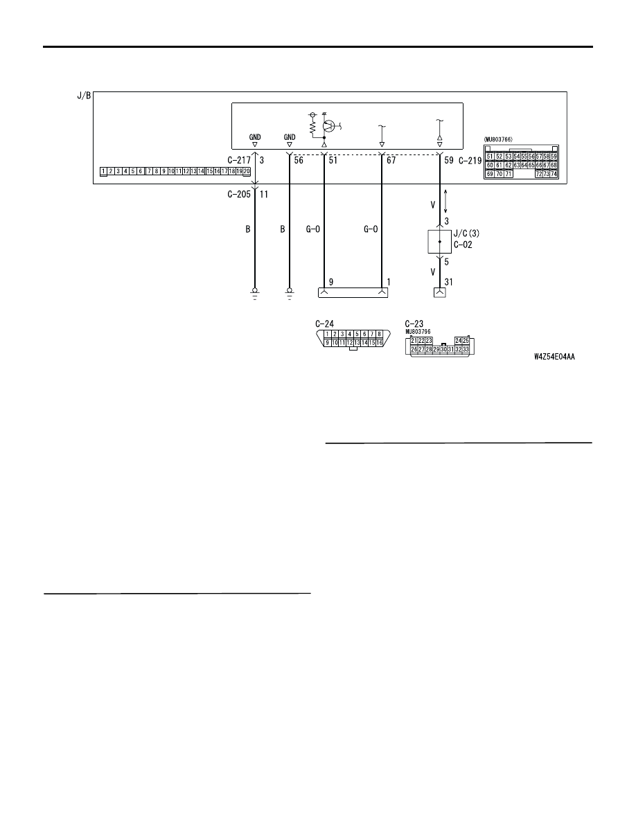
SMART WIRING SYSTEM (SWS) NOT USING SWS MONITOR
54B-49
COMMENTS ON TROUBLE SYMPTOM
It is suspected that the power supply circuit to the
ETACS-ECU is defective, or the wiring harness
between the diagnosis connector and the
ETACS-ECU or their connector(s) is damaged.
NOTE: If the wiring harness between the
ETACS-ECU and body earth is defective, also check
C-217 ETACS-ECU connector terminal No.3, and
repair if necessary.
POSSIBLE CAUSES
•
Malfunction of the ETACS-ECU
•
Damaged harness wires and connectors
DIAGNOSTIC PROCEDURE
Step 1. Check that the MUT-II/III communicates
with the other systems.
Use the MUT-II/III to confirm that it communicates
with the engine-ECU.
Q: Is the check result normal?
YES :
Go to Step 2.
NO :
Diagnose the engine control system by
referring to
<4G63> or
<4G69>.
Step 2. Check that the MUT-II/III can
communicate with the system.
When the ignition switch is turned ON, check if the
MUT-II/III can communicate with the system.
Q: Is the check result normal?
YES :
Refer to inspection procedure A-2 "Check
the ETACS-ECU battery power supply
circuit"
NO :
Go to Step 3.
ETACS-
ECU
DIAGNOSIS
CONNECTOR
DIAGNOSIS
CONNECTOR
FRONT SIDE
FRONT SIDE
Wire colour code
B : Black LG : Light green G : Green L : Blue
W : White Y : Yellow SB : Sky blue BR : Brown
O : Orange GR : Gray R : Red P : Pink V : Violet
MUT-II Communication and ETACS-ECU Ground Circuit <RHD>