Mitsubishi Outlander (2003+). Manual - part 439


  Index      Mitsubishi     Mitsubishi Outlander - service repair manual 2003 year


Search            


Content   ..  437  438  439  440   ..


Mitsubishi Outlander (2003+). Manual - part 439


CHECK TROUBLE BY USING THE INPUT SIGNAL CHECK

SMART WIRING SYSTEM (SWS) NOT USING SWS MONITOR

54B-45

CHECK TROUBLE BY USING THE INPUT SIGNAL CHECK

M1549024200255

<Pulse check>

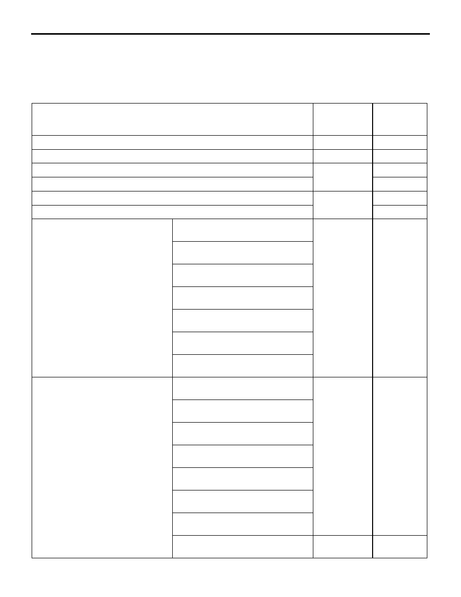
If a problem is found in the Service Data inspection, observe the table below.

Symptom

Inspection 
procedure 
number

Reference 
page

The ignition switch (ACC) signal is not received.

N-1

P.54B-298

The ignition switch (IG1) signal is not received.

N-2

P.54B-301

The back-up lamp switch signal is not received. <M/T>

N-3

P.54B-304

The inhibitor switch (reverse position) signal is not received. <A/T>

P.54B-309

The front door switch (LH) signal is not received. <L.H. drive vehicles>

N-4

P.54B-315

The front door switch (RH) signal is not received. <R.H. drive vehicles>

P.54B-317

Column switch (lighting and 
turn-signal lamp switch)

The tail lamp switch signal is not 
received.

N-5

P.54B-319

The headlamp switch signal is not 
received.
The dimmer switch signal is not 
received.
The passing switch signal is not 
received.
The turn-signal lamp switch (LH) 
signal is not received.
The turn-signal lamp switch (RH) 
signal is not received.
The headlamp washer switch signal 
is not received.

Column switch (windshield 
wiper/washer and rear wiper washer 
switch)

The windshield mist wiper switch 
signal is not received.

N-6

P.54B-320

The windshield intermittent wiper 
switch signal is not received.
The windshield low-speed wiper 
switch signal is not received.
The windshield high-speed wiper 
switch signal is not received.
The windshield washer switch signal 
is not received.
The rear wiper switch signal is not 
received.
The rear washer switch signal is not 
received.
The windshield intermittent wiper 
volume signal is not received.

N-7

P.54B-321

CHECK TROUBLE BY USING THE INPUT SIGNAL CHECK

SMART WIRING SYSTEM (SWS) NOT USING SWS MONITOR

54B-46

Power window main switch

When the power window main switch 
is operated, the switch signals are 
not received.

N-8

P.54B-325

The key reminder switch signal is not received.

N-9

P.54B-334

The hazard warning lamp switch signal is not received.

N-10

P.54B-338

All the door switch signals are not received. <L.H. drive vehicles>

N-11

P.54B-342

All the door switch signals are not received. <R.H. drive vehicles>

P.54B-346

The driver's door lock actuator switch signal is not received. <L.H. drive 
vehicles>

N-12

P.54B-350

The driver's door lock actuator switch signal is not received. <R.H. drive 
vehicles>

P.54B-354

The vehicle speed signal is not received. <M/T>

N-13

P.54B-358

The vehicle speed signal is not received. <A/T>

P.54B-363

Each switch signal of the keyless entry transmitter is not received.

N-14

P.54B-366

The front fog lamp switch signal is not received.

N-15

P.54B-367

The rear fog lamp switch signal is not received.

N-16

P.54B-371

The interior lamp loaded signal is not detected.

N-17

P.54B-375

The front passenger’s door lock key cylinder switch signal is not detected. 
<L.H. drive vehicles>

N-18

P.54B-380

The front passenger’s door lock key cylinder switch signal is not detected. 
<R.H. drive vehicles>

P.54B-383

Symptom

Inspection 
procedure 
number

Reference 
page

OPERATION AND FUNCTION QUICK-REFERENCE TABLE FOR INPUT SIGNAL INSPECTION PROCEDURES

SMART WIRING SYSTEM (SWS) NOT USING SWS MONITOR

54B-47

OPERATION AND FUNCTION QUICK-REFERENCE TABLE 

FOR INPUT SIGNAL INSPECTION PROCEDURES

M1549020300250

If troubles have occurred in the functions which use the SWS simultaneously, observe the table below to 
check input signals.
(This table shows only the input signals which will cause troubles in at least two functions simultaneously).

Function

N-1

N-2

N-4

N-5

N-6

N-9

N-11

N-12

N-13

N-17

Lamp reminder function

×

×

×

Control of central door 
locking

×

Key reminder function

×

×

×

Door locking released due to 
impact detection.

Keyless entry system

×

×

×

×

Keyless entry hazard 
warning lamp answerback

Power window control

×

Control of windshield wiper 
washer

×

×

×

Rear wiper washer control

×

×

Ignition key cylinder 
illumination lamp function

×

×

×

×

Headlamp control

×

×

Tail lamp control

×

×

Headlamp 
automatic-shutdown function

×

×

×

Fog lamp control

×

Turn-signal lamp control

×

×

Dome lamp control

×

×

×

×

×

×

Interior lamp 
automatic-shutdown function

×

×

Door-ajar indicator lamp

×

×

SYMPTOM PROCEDURES

SMART WIRING SYSTEM (SWS) NOT USING SWS MONITOR

54B-48

SYMPTOM PROCEDURES

INSPECTION PROCEDURE A-1: Communication with the MUT-II/III is not possible

CAUTION

Whenever the ECU is replaced, ensure that the 
power supply circuit, the earthing circuit and the 
communication circuit are normal.

ETACS-
ECU

DIAGNOSIS 
CONNECTOR

DIAGNOSIS 
CONNECTOR

FRONT SIDE

FRONT SIDE

Wire colour code
B : Black     LG : Light green     G : Green     L : Blue      
W : White     Y : Yellow     SB : Sky blue     BR : Brown 
O : Orange     GR : Gray     R : Red     P : Pink     V : Violet        

MUT-II Communication and ETACS-ECU Earth Circuit <LHD>


Content   ..  437  438  439  440   ..