Mitsubishi Outlander (2003+). Manual - part 391


  Index      Mitsubishi     Mitsubishi Outlander - service repair manual 2003 year


Search            


Content   ..  389  390  391  392   ..


Mitsubishi Outlander (2003+). Manual - part 391


TROUBLESHOOTING

SUPPLEMENTAL RESTRAINT SYSTEM (SRS)

52B-163

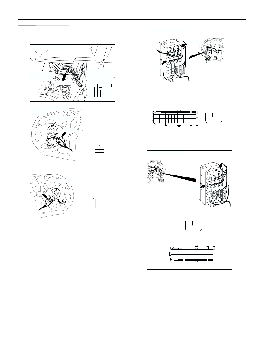
STEP 7. Connector check: SRS-ECU connector 
C-115, ignition switch connector C-303, junction 
block connector C-203 and C-205

Q: Is the check result normal?

YES : 

Check the harness wires for open or short 

circuit between SRS-ECU connector C-115 
(terminal No.13 and 16) and ignition switch 
connector C-303 (terminal No.2), and repair 
if necessary. Then go to Step 8.

NO : 

Repair or replace it. Then go to Step 8.

AC301661AC

Harness side
connector
(front view)

Connector: C-115

SRS-ECU

C-115 (Y)

Center lower
panel

1110 9

1

2

3

1413

12

4

5

6

16

8

15

7

17

18

19

20

AC301399

Connector: C-303

Clock spring

C-303

AK

Harness side
connector
(front view)

2
5

6

3

4

1

<LHD>

AC308778

Connector: C-303 <RHD>

Clock spring

AG

Harness side

2
5

6

3

4

1

AC210475

Connectors: C-203, C-205 <LHD>

BC

Junction Block (Front View)

C-205

C-203

Harness side

C-203

C-205

4

6 5

3

2

1

21

7

16 15

17

18

20 19

1

2

3

4

5

6

23 22

24

25

28

26

27

9

8

10

11

14

12

13

AC308773

Connectors: C-203, C-205 <RHD>

AK

Junction Block (Front View)

C-205

C-203

Harness side

C-203

C-205

4

6 5

3

2

1

21

7

16 15

17

18

20 19

1

2

3

4

5

6

23 22

24

25

28

26

27

9

8

10

11

14

12

13

Harness side

TROUBLESHOOTING

SUPPLEMENTAL RESTRAINT SYSTEM (SRS)

52B-164

STEP 8. Retest the system.

Q: Does the MUT-II/III communicate normally with the 

SRS system?

YES : 

The procedure is complete (If no 

malfunctions are found in all steps, an 
intermittent malfunction is suspected. Refer 
to GROUP 00 

 How to Use 

Troubleshooting/Inspection Service Points 

P.00-6

).

NO : 

There is no action to be taken.

SRS MAINTENANCE

SUPPLEMENTAL RESTRAINT SYSTEM (SRS)

52B-165

SRS MAINTENANCE

M1524003900326

The SRS must be inspected by an authorized dealer 
10 years after the date of vehicle registration.

SRS WARNING LAMP CHECK

Turn the ignition key to the "ON" position. Does the 
SRS warning lamp illuminate for about 7 seconds, 
turn off and then remain extinguished for at least 5 
seconds? If yes, SRS system is functioning properly. 
If no, consult page 

P.52B-11

.

SRS COMPONENT VISUAL CHECK

DANGER

Wait at least 60 seconds after disconnecting 
the battery cable before doing any further 
work (Refer to 

P.52B-3

).

Turn the ignition key to the "LOCK" position, 
disconnect the negative battery cable and tape the 
terminal.

FRONT IMPACT SENSORS

1. Check the front side member and front impact 

sensor for deformation or rust.

2. Check the front impact sensor for dents, cracks, 

deformation or rust.

3. Check the sensor harnesses for binding, the 

connectors for damage, and the terminals for 
deformation.

NOTE: The figures show front impact sensors (LH). 
The side impact sensors (RH) is symmetrical with the 
side impact sensors (LH).

AC301667

SRS warning lamp

AB

AC300580AB

Insulating tape

Battery

Battery cable

AC300581AB

Front impact sensors

SRS MAINTENANCE

SUPPLEMENTAL RESTRAINT SYSTEM (SRS)

52B-166

SIDE IMPACT SENSOR

WARNING

The SRS may not activate if the impact 
sensors are not installed properly, which 
could result in serious injury or death to the 
vehicle's driver or front passenger.

1. Check the centre pillar for deformation or rust.
2. Check the side impact sensors for dents, cracks, 

deformation and rust.

3. Check the connector for damage and the 

terminals for deformation.

NOTE: The figures show side impact sensors (RH). 
The side impact sensors (LH) is symmetrical with the 
side impact sensors (RH).

SRS CONTROL UNIT (SRS-ECU) 

WARNING

The SRS may not activate if the SRS-ECU is 
not installed properly, which could result in 
serious injury or death to the vehicle's driver 
or front passenger.

1. Check the SRS-ECU case and brackets for dents, 

cracks, deformation or rust.

2. Check the connector for damage, and check the 

terminals for deformation or rust.
Replace the SRS-ECU if it fails the visual checks 
above (Refer to 

P.52B-178

).

AIR BAG MODULES, STEERING WHEEL 
AND CLOCK SPRING 

WARNING

The removed air bag module should be 
stored in a clean, dry place with the pad 
cover face up.

1. Remove the air bag module, steering wheel and 

clock spring (Refer to 

P.52B-179

).

2. Check the pad cover for dents, cracks or 

deformation.

3. Check the connector for damage and deformed 

terminals, and check the harness for binding.

4. Check the air bag inflator case for dents, cracks or 

deformation.

AC201282

Center pillar

Side impact sensor

AF

AC300582

SRS-ECU

AB

AC300170AB

<Driver's side>

<Front passenger's side>

Inflator case

Connector

Connector

Inflator case


Content   ..  389  390  391  392   ..