Mitsubishi Outlander (2003+). Manual - part 390


  Index      Mitsubishi     Mitsubishi Outlander - service repair manual 2003 year


Search            


Content   ..  388  389  390  391   ..


Mitsubishi Outlander (2003+). Manual - part 390


TROUBLESHOOTING

SUPPLEMENTAL RESTRAINT SYSTEM (SRS)

52B-159

SYMPTOM PROCEDURES

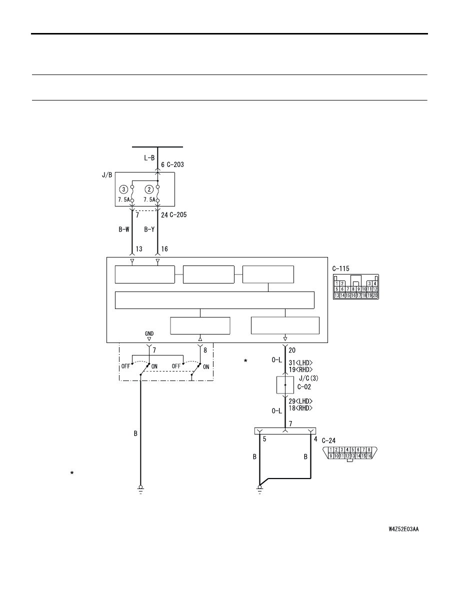
INSPECTION PROCEDURE 1: Communication with MUT-II/III is not possible. (Communication is not 
possible with SRS).

POWER SOURCE
CIRCUIT

BACK-UP 
CAPACITOR

D.C.-D.C. 
CONVERTER

IGNITION 
SWITCH (IG1)

SRS-ECU

MICROCOMPUTER

CONNECTOR
LOCK
SWITCH

WARNING LAMP
DRIVE CIRCUIT

NOTE

CONNECTOR
COUPLED: ON
CONNECTOR
UNCOUPLED: OFF

DIAGNOSIS 
CONNECTOR

MUT-II INTERFACE
CIRCUIT

FRONT SIDE

Wire colour code
B : Black     LG : Light green     G : Green     L : Blue     W : White     Y : Yellow     SB : Sky blue
BR : Brown     O : Orange     GR : Gray     R : Red     P : Pink     V : Violet   

SRS-ECU Power Supply Circuit

TROUBLESHOOTING

SUPPLEMENTAL RESTRAINT SYSTEM (SRS)

52B-160

OPERATION

The SRS-ECU is powered from the ignition 
switch (IG1).

The SRS-ECU power is supplied from two 
circuits. Even if one circuit is shut off, the air bag 
can inflate.

The SRS system diagnosis can be done by 
connecting MUT-II/III to the diagnosis connector.

COMMENTS ON TROUBLE SYMPTOM
If communication is not possible with the SRS only, 
the cause is probably an open circuit in the on-board 
diagnostic output circuit of the SRS or in the power 
circuit (including earth circuit).

PROBABLE CAUSES

Damaged wiring harnesses or connectors

Malfunction of the SRS-ECU

DIAGNOSIS PROCEDURE

STEP 1. Check that the MUT-II/III can 
communicate with the other systems.

Q: Can the MUT-II/III communicate with the other 

systems?
YES : 

Go to Step 2.

NO : 

Refer to GROUP 13A 

 Troubleshooting 

P.13A-190

.

STEP 2. Measure the resistance between 
SRS-ECU connector C-115 (terminal No.20) and 
diagnosis connector C-24 (terminal No.7) 

(1) Disconnect SRS-ECU connector C-115 and 

diagnosis connector C-24, and measure at the 
wiring harness side. 

CAUTION

Do not insert a test probe into the terminal from 
of the SRS-ECU connector C-115 its front side 
directly as the connector contact pressure may 
be weakened.
(2) Measure the resistance between the following 

terminals. 

SRS-ECU connector C-115 (terminal No.20) 
and diagnosis connector C-24 (terminal No.7)

OK: Less than 2 

Q: Is the check results normal?

YES : 

Go to Step 3.

NO : 

Go to Step 5.

AC301661AC

Harness side
connector
(front view)

Connector: C-115

SRS-ECU

C-115 (Y)

Center lower
panel

1110 9

1

2

3

1413

12

4

5

6

16

8

15

7

17

18

19

20

AC208056

CONNECTOR: C-24

AF

C-24 (B)

Center lower panel

1 2 3 4 5 6 7 8
9 10 11121314 15 16

Harness side
connector
(front view)

131415 1617 1819 20

5 6 7 8 9 10 1112

1 2

3 4

1 2 3 4 5 6 7 8
9 10 11121314 15 16

AC201667AI

C-24 Connector
(front view)

C-115 Harness side
connector (rear view)

TROUBLESHOOTING

SUPPLEMENTAL RESTRAINT SYSTEM (SRS)

52B-161

STEP 3. Check the earth circuit to the SRS-ECU.

(1) Disconnect SRS-ECU connector C-115, and 

measure at the wiring harness side.

CAUTION

Do not insert a test probe into the terminal from 
its front side directly as the connector contact 
pressure may be weakened.
(2) Check for continuity between terminal 7 and body 

earth.

OK: Less than 2 

Q: Is the check result normal?

YES : 

Go to Step 4.

NO : 

Go to Step 6.

STEP 4. Check the power supply circuit to the 
SRS-ECU.

(1) Disconnect SRS-ECU connector C-115, and 

measure at the wiring harness side.

(2) Connect the negative battery terminal.
(3) Turn the ignition switch to the "ON" position.

CAUTION

Do not insert a test probe into the terminal from 
its front side directly as the connector contact 
pressure may be weakened.
(4) Measure the voltage between terminals 13, 16 

and body earth.

OK: 9 V or more

Q: Is the check result normal?

YES : 

Recheck the trouble symptom. If it is not 

solved, replace the SRS-ECU (Refer to 

P.52B-178

). Then go to Step 8.

NO : 

Go to Step 7.

AC301661

Connector: C-115

AB

SRS-ECU

C-115 (Y)

Center lower
panel

13 14 15 16 17 18 19 20

5 6 7 8 9 10 11 12

1 2

3 4

AC301059AB

C-115 Harness side
connector (rear view)

AC301661

Connector: C-115

AB

SRS-ECU

C-115 (Y)

Center lower
panel

13 14 15 16 17 18 19 20

5 6 7 8 9 10 11 12

1 2

3 4

AC301060 AB

C-115 Harness side
connector (rear view)

TROUBLESHOOTING

SUPPLEMENTAL RESTRAINT SYSTEM (SRS)

52B-162

STEP 5. Connector check: SRS-ECU connector 
C-115, diagnosis connector C-24 and joint 
connector (3) C-02

Q: Is the check result normal?

YES : 

Check the harness wires for open or short 

circuit between SRS-ECU connector C-115 
(terminal No.20) and diagnosis connector 
C-24 (terminal No.7), and repair if 
necessary. Then go to Step 8.

NO : 

Repair or replace it. Then go to Step 8.

STEP 6. Connector check: SRS-ECU connector 
C-115 and earth

Q: Is the check result normal?

YES : 

Check the harness wire for open circuit 

between SRS-ECU connector C-115 
(terminal No.7) and earth, and repair if 
necessary. Then go to Step 8.

NO : 

Repair or replace it. Then go to Step 8.

AC301661AC

Harness side
connector
(front view)

Connector: C-115

SRS-ECU

C-115 (Y)

Center lower
panel

1110 9

1

2

3

1413

12

4

5

6

16

8

15

7

17

18

19

20

AC208056

CONNECTOR: C-24

AF

C-24 (B)

Center lower panel

1 2 3 4 5 6 7 8
9 10 11121314 15 16

Harness side
connector
(front view)

AC301395AS

33

22

11

28

17

16

15

14

13

12

25

2324

2627

3

1 2

4 5

21

20

19

18

2930

32

31

7

6

8

10

9

Connector: C-02 <LHD>

AC308769

AD

33

22

11

28

17

16

15

14

13

12

25

2324

2627

3

1 2

4 5

21

20

19

18

2930

32

31

7

6

8

10

9

Connector: C-02 <RHD>

AC301661AC

Harness side
connector
(front view)

Connector: C-115

SRS-ECU

C-115 (Y)

Center lower
panel

1110 9

1

2

3

1413

12

4

5

6

16

8

15

7

17

18

19

20

AC208080AG

Blower
assembly

<LHD>

AC208081

AC

<RHD>


Content   ..  388  389  390  391   ..