Mitsubishi Outlander (2003+). Manual - part 287


  Index      Mitsubishi     Mitsubishi Outlander - service repair manual 2003 year


Search            


Content   ..  285  286  287  288   ..


Mitsubishi Outlander (2003+). Manual - part 287


ON-VEHICLE SERVICE

POWER STEERING

37-7

ON-VEHICLE SERVICE

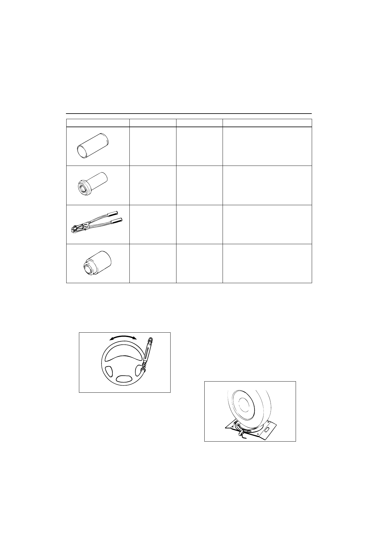
STEERING WHEEL FREE PLAY CHECK

M1372001000270

1. With the engine running (hydraulic operation), set 

the front wheels straight ahead.

2. Measure the play on the steering wheel 

circumference before the wheels start to move 
when slightly moving the steering wheel in both 
directions.

Limit: 30 mm

3. When the play exceeds the limit, check for the 

play on the steering shaft and steering linkage 
connection. Correct or replace.

4. If the free play still exceeds the limit value, set the 

steering wheel straight ahead with the engine 
stopped. Load 5 N towards the steering wheel 
circumference and check the play.

Standard value (steering wheel play with the 
engine stopped): 10 mm or less

5. If the play exceeds the standard value, remove the 

steering gear (Refer to 

3

37


). and check the 

total pinion torque (Refer to 

3

37


).

STEERING ANGLE CHECK

M1372001100341

MB991317

Seal ring installer

Seal ring installation

MB990941

Torque tube 
bearing installer

Lower oil seal installation

MB991561

Boot band crimping 
tool

Bellows band installation

MB990776

Front axle base

Tie rod end ball joint dust cover 
installation

Tool

Number

Name

Use

MB991317

MB990941

MB991561

MB990776

ACX01122 AB

AC000756AB

ON-VEHICLE SERVICE

POWER STEERING

37-8

1. Place the front wheel on a turning radius gauge 

and measure the steering angle.

Standard value:

2. If the steering angle is not within the standard 

value, adjust the toe-in as follows. 

Standard value:
at the centre of tyre tread: 1 

–

 2 mm

Toe angle (per wheel): 0

•

03’ 

–

 05’

3. Loosen the jam nut, and unclip the bellows.
4. Adjust the toe-in by turning the left and right tie 

rod turnbuckles by the same amount (in opposite 
directions).

NOTE: The toe will move out as the left 
turnbuckle is turned toward the front of the vehicle 
and the right turnbuckle is turned toward the rear 
of the vehicle.

5. Tighten the jam nut to the specified torque, and 

tighten the bellows by the clip.

Tightening torque: 52 

–

 2 N

¼

m

6. Recheck the steering angle.

TIE ROD END BALL JOINT STARTING 
TORQUE CHECK

M1372001500275

CAUTION

œ

Do not remove the nut from ball joint. Loosen 
it and use special tool to avoid possible 
damage to the ball joint threads.

œ

Hang special tool with cord to prevent it from 
falling. 

1. Install special tool ball joint remover (MB991897) 

as shown in the figure.

2. Turn the bolt and knob as necessary to make the 

jaws of special tool parallel, tighten the bolt by 
hand and confirm that the jaws are still parallel.

NOTE: When adjusting the jaws in parallel, make 
sure the knob is in the position shown in the 
figure.

3. Tighten the bolt with a wrench to disconnect the 

tie rod end.

Item

Specification

Inside wheel

34

•

50’ 

–

 1

•

30’

Outside wheel 
(reference)

29

•

20’

AC006074 AB

Jam nut

Clip

AC208247AD

Cord

Bolt

MB991897

Nut

Ball joint

AC106821

Knob

Parallel

Bolt

Good

Bad

AB

ON-VEHICLE SERVICE

POWER STEERING

37-9

4. Move the ball joint stud several times and install 

the nut on the stud. Using special tool preload 
socket (MB990326), measure the ball joint 
starting torque.

Standard value: 0.5 

-

 2.5 N

¼

m

5. If the starting torque exceeds the standard value, 

replace the tie rod end.

6. If the starting torque is under the standard value, 

check the ball joint for axial play or ratcheting. If 
no axial play or ratcheting, the ball joint can be re-
used.

CAUTION

Always use a new ball joint nut as it is a self-
locking nut.

7. Install the tie rod end to the knuckle, then tighten a 

new self-locking nut to the specified torque.

Tightening torque: 25 

–

 5 N

¼

m

STATIONARY STEERING EFFORT CHECK

M1372001700310

1. With the vehicle stopped on a flat and paved 

surface, turn the steering wheel to the straight 
ahead position.

2. Start the engine and set the engine idle speed.

Standard value: 750 

–

 100 r/min

3. Attach a spring balance to the outer 

circumference of the steering wheel and measure 
the steering force required to turn the steering 
wheel from the straight ahead position to the left 
and right (within a range of 1.5 turns). Also check 
to be sure that there is no significant change in 
the required steering effort.

Standard value:
Steering effort: 29 N or less
Fluctuation allowance: 5.9 N or less

4. If the measured value exceeds the standard 

value, check and adjust the related parts.

STEERING WHEEL RETURN TO CENTRE 
CHECK

M1372001800287

Conduct a road test:
1. Make both gradual and sudden turns and check 

the steering wheel return. 

2. At a vehicle speed of approximately 35 km/h, turn 

the steering wheel 90

•

, hold a few seconds, then 

release. If the steering wheel then returns 70

•

 or 

more, the return can be judged satisfactory.

NOTE: There will be a momentary feeling or 
"heaviness" when the wheel is turned quickly, but 
this is not abnormal (Oil pump discharge amount 
is especially apt to be insufficient during idling). 

DRIVE BELT TENSION CHECK

M1372001900240

Refer to GROUP 11A, On-vehicle Service 

-

 Drive 

Belt Tension Check 

3

11A


.

FLUID LEVEL CHECK

M1372002000262

1. Park the vehicle on a flat, level surface.
2. Start the engine, and then turn the steering wheel 

several times to raise the temperature of the fluid 
to approximately 50 

-

 60

•

C.

3. With the engine running, turn the wheel all the 

way to the left and right several times.

ACX01129 AB

MB990326

ACX01122 AB

ACX01130AB

70˚

70˚

ON-VEHICLE SERVICE

POWER STEERING

37-10

4. Check the fluid in the oil reservoir for foaming or 

milkiness. Check the difference of the fluid level 
when the engine is stopped, and while it is 
running. If the change of the fluid level is 5 mm or 
more, air bleeding should be done.

FLUID REPLACEMENT

M1372002100311

1. Raise and support the front wheels.

2. Disconnect the return hose connection, and then 

connect a vinyl hose to the return hose, and drain 
the fluid into a container.

3. Disconnect the ignition coil connectors (Refer to 

GROUP 16, Ignition Coil 

3

16


).

4. While operating the starter motor intermittently, 

turn the steering wheel all the way to the left and 
right several times to drain all of the fluid.

5. Connect the return hose securely, and then 

secure with the clip.

6. Fill the oil reservoir with specified fluid up to the 

lower position of the filler, and then bleed the air.

Specified fluid: ATF DEXRON III or DEXRON 
II

POWER STEERING SYSTEM AIR 
BLEEDING

M1372002200318

Perform air bleeding procedure as necessary after 
replacing the steering gear or the steering fluid lines.
1. Raise and support the front wheels.

2. Disconnect the ignition coil connectors (Refer to 

GROUP 16, Ignition Coil 

3

16


).

CAUTION

Perform air bleeding only while cranking the 
engine. If air bleeding is performed while the 
engine is running, air could enter the fluid. 
During air bleeding, refill the steering fluid 
supply so that the level never falls below the 
"MIN" mark on the oil reservoir.

3. Turn the steering wheel all the way to the left and 

right five or six times while using the starter motor 
to crank the engine intermittently several times 
(for 15 to 20 seconds).

4. Connect the ignition coil connectors (Refer to 

GROUP 16, Ignition Coil 

3

16


).

5. Start the engine (idling).
6. Turn the steering wheel to the left and right until 

there are no air bubbles in the oil reservoir.

7. Confirm that the fluid is not milky, and that the 

level is between "MAX" and "MIN" marks.

8. Confirm that there is very little change in the fluid 

level when the steering wheel is turned left and 
right.

CAUTION

If the fluid level rises suddenly after the engine is 
stopped, the air has not been completely bled. If 
air bleeding is not complete, there will be 
abnormal noises from the pump and the flow-
control valve, and this condition could cause 
reduce the life of the power steering 
components.

9. Confirm that the change in the fluid level is no 

more than 5 mm when the engine is stopped and 
when it is running.

10.If the change of the fluid level is 5 mm or more, 

the air has not been completely bled from the 
system. The air bleeding procedure must be 
repeated.

ACX01131

While engine running

While engine stopped

AC

Fluid level change: Within 5 mm

AC100369AB

Return hose

Return hose

Vinyl hose

ACX01131

While engine running

While engine stopped

AC

Fluid level change: Within 5 mm


Content   ..  285  286  287  288   ..