Mitsubishi Outlander (2003+). Manual - part 246
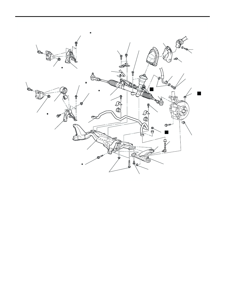
CROSSMEMBER
POWER PLANT MOUNT
32-15
AC309433
1
2
4
9
10
11
186 ± 10 N·m ²
167 ± 9 N·m
49 ± 10 N·m
108 ± 10 N·m
25 ± 5 N·m
21 ± 4 N·m
18 ± 2 N·m
N
N
AB
8
12
N
7
5
6
57 ± 7 N·m
18
19
20
70 ± 10 N·m
70 ± 10 N·m
12 ± 2 N·m
21 ± 4 N·m
3
39 ± 5 N·m
<4WD>
5.0 ± 1.0 N·m
14
15
17
45 ± 5 N·m ¹
52 ± 7 N·m ¹
52 ± 7 N·m ¹
13
52 ± 7 N·m ¹
<L.H. drive vehicles>
45 ± 5 N·m ¹
16
<2WD>
Removal steps
1.
Lower arm and knuckle connection
>>B<<
2.
Self-locking nut
3.
Stabilizer link assembly
4.
Lower arm assembly
5.
Return hose connection
6.
Eye bolt
7.
Pressure hose connection
8.
Gasket
9.
Shaft cover
10. Steering shaft assembly and gear
box connecting bolt
11. Self-locking nut
<<A>>
12. Tie rod end and knuckle connection
13. Engine rear roll stopper bracket
connecting bolt <2WD>
14. Engine roll stopper rod connecting
bolt <4WD>
15. Engine roll stopper rod assembly
<4WD>
<<B>>
•
Crossmenber, engine rear roll
stopper bracket, stabilizer bar and
steering gear and linkage assembly
<2WD>
<<B>>
•
Crossmenber, engine roll stopper
rod bracket, stabilizer bar and
steering gear and linkage assembly
<4WD>
16. Engine rear roll stopper bracket
<2WD>
17. Engine roll stopper rod bracket
<4WD>
>>A<<
18. Stabilizer bar
19. Steering gear and linkage
20. Crossmember
Removal steps (Continued)