Mitsubishi Outlander (2003+). Manual - part 245
ENGINE ROLL STOPPER, CENTREMEMBER <4G63>
POWER PLANT MOUNT
32-11
INSTALLATION SERVICE POINT
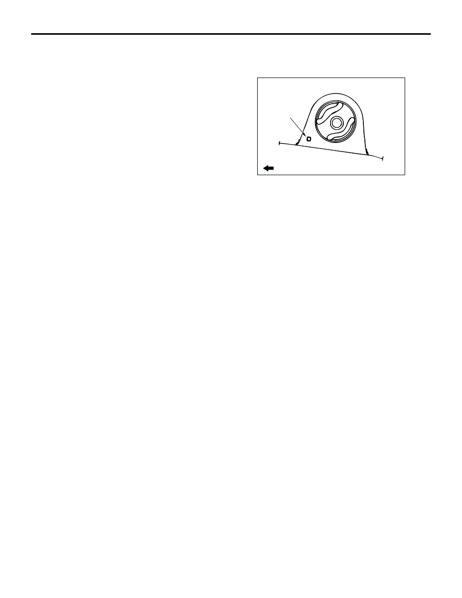
>>A<< ENGINE ROLL STOPPER BRACKET
INSTALLATION
Install the engine roll stopper bracket so that its hole
points towards the front side of the vehicle.
INSPECTION
M1321002400057
•
Check the roll stopper for cracks, separation or
deformation.
•
Check the centremember for cracks or damage.
Engine roll stopper rod and
bracket removal steps <4WD>
•
Front exhaust pipe (Refer to
GROUP 15, Exhaust pipe
5.
Engine roll stopper rod connecting
bolt
11. Engine roll stopper rod assembly
12. Engine roll stopper rod bracket and
crossmember assembly (Refer to
).
13. Engine roll stopper rod bracket
14. Crossmember assembly
AC208360
Front of vehicle
Hole
AC