Mitsubishi Outlander (2003+). Manual - part 175
CENTER DIFFERENTIAL
MANUAL TRANSMISSION OVERHAUL
22B-53
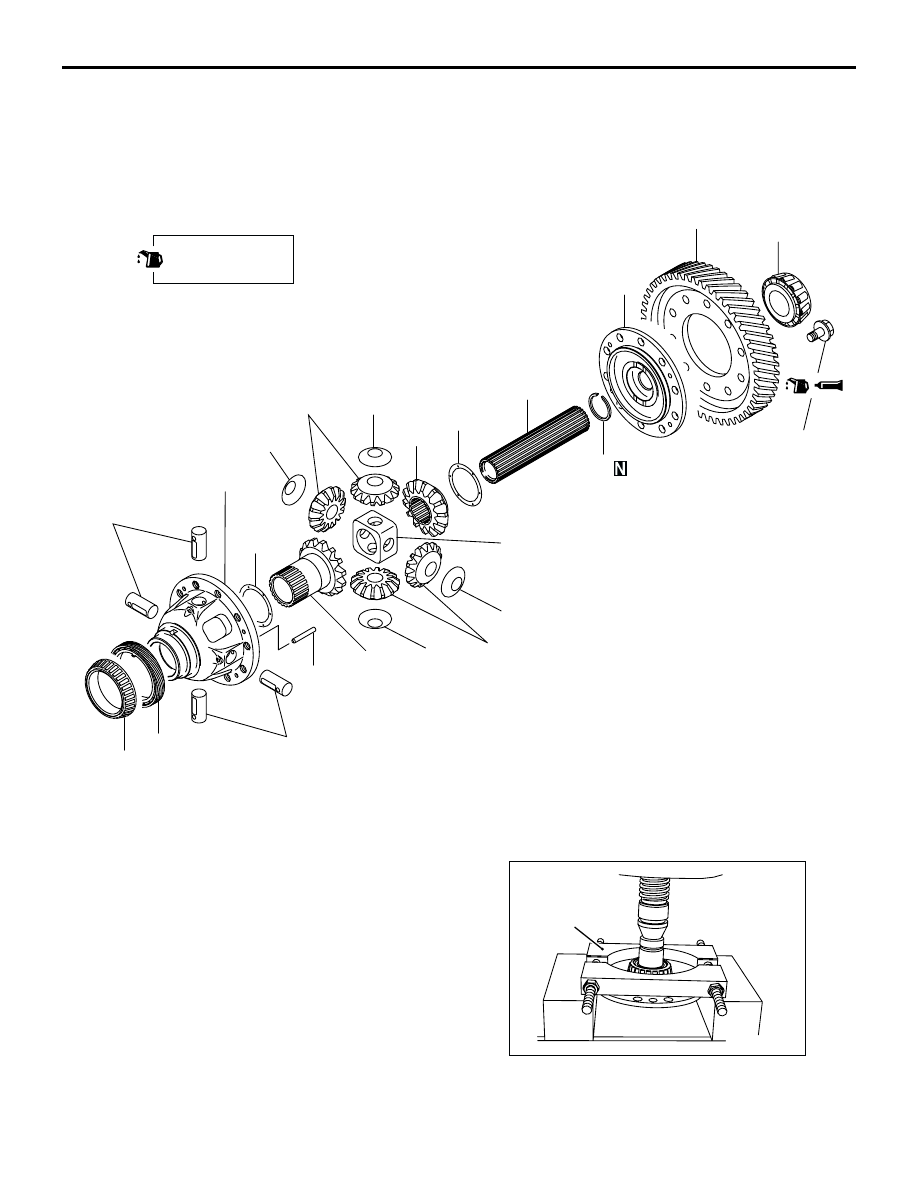
CENTER DIFFERENTIAL
DISASSEMBLY AND REASSEMBLY
M1222002800051
<W5M42>
DISASSEMBLY SERVICE POINTS
<<A>> TAPER ROLLER BEARING REMOVAL
1. Support the taper roller bearing with special tool
bearing remover (MD998917), and then set them
on the press.
AK204225
1
2
5
4
16
8
15
12
11
10
12
13
9
6
7
12
14
17
12
11
9
3
132 ± 5 N·m
AB
Apply gear oil to all
moving parts before
installation.
Disassembly steps
>>D<<
1.
Center differential drive gear
>>C<<
2.
Center differential flange
<<A>>
>>B<<
3.
Taper roller bearing
>>C<<
4.
Snap ring
>>C<<
5.
Front output shaft
>>C<<
6.
Spacer
>>C<<
7.
Side gear
>>C<<
8.
Lock pin
>>C<<
9.
Pinion shaft
>>C<<
10. Pinion shaft holder
>>C<<
11. Pinions
>>C<<
12. Washers
>>C<<
13. Side gear
>>C<<
14. Spacer
<<B>>
>>A<<
15. Taper roller bearing
16. Speed meter drive gear
17. Differential case
AK204264AB
MD998917