Mitsubishi Outlander (2003+). Manual - part 112


  Index      Mitsubishi     Mitsubishi Outlander - service repair manual 2003 year


Search            


Content   ..  110  111  112  113   ..


Mitsubishi Outlander (2003+). Manual - part 112


ON-VEHICLE SERVICE

MULTIPORT FUEL INJECTION (MFI)

13A-311

(7) Connect the fuel pump assembly <2WD> or 

the fuel tank pump and gauge assembly 
<4WD> connector.

(8) Install the service hole cover and rear seat 

assembly (Refer to GROUP 52A, Rear Seat 
Assembly Removal and Installation 
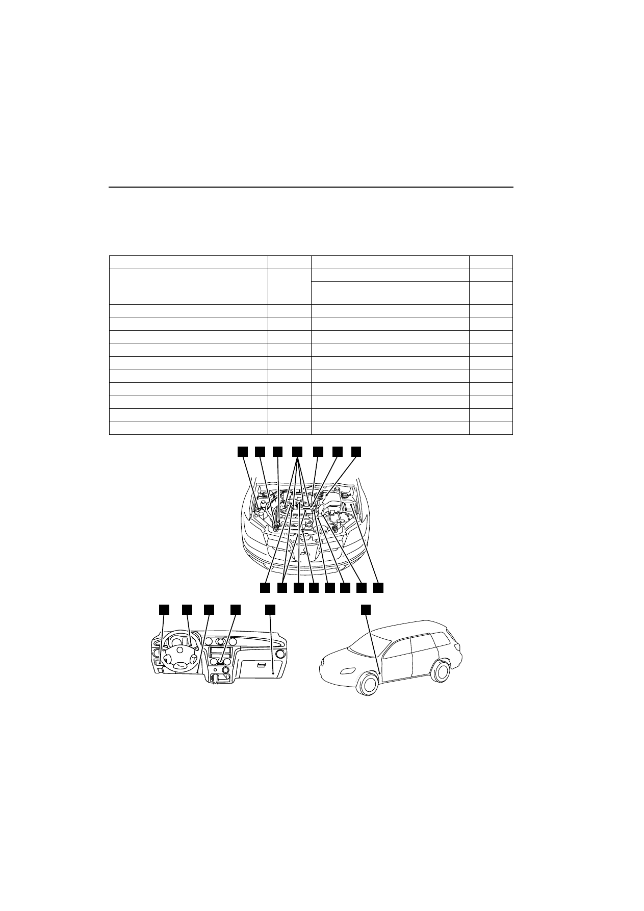
P.52A-25

).

COMPONENT LOCATION

M1131002100622

Name

Symbol

Name

Symbol

Air flow sensor
(with intake air temperature sensor and 
barometric pressure sensor)

G

Engine-ECU

T

Engine warming lamp 
(check engine lamp)

Q

A/C relay

O

Fuel pump relay (1) and (2)

P

A/C switch

S

Idle speed control servo

F

A/C pressure sensor

A

Ignition coil

I

Camshaft position sensor

L

Injector

D

Crank angle sensor

C

Oxygen sensor (front)

K

Detonation sensor

H

Oxygen sensor (rear)

U

Diagnosis connector

R

Power steering fluid pressure switch

B

EGR control solenoid valve

J

Purge control solenoid valve 

J

Engine control relay

O

Throttle position sensor

E

Engine coolant temperature sensor

M

Vehicle speed sensor

N

AK300351

T

R

S

Q

P

U

E

G

F

C

B

A

D

J

I

H

M

N

O

L

K

AB

ON-VEHICLE SERVICE

MULTIPORT FUEL INJECTION (MFI)

13A-312

ENGINE CONTROL RELAY CONTINUITY 
CHECK

M1131050000185

FUEL PUMP RELAY CONTINUITY CHECK

M1131033000193

INTAKE AIR TEMPERATURE SENSOR 
CHECK

M1131002800364

1. Disconnect the air flow sensor connector.
2. Measure resistance between terminals No. 5 and 

No. 6.

Standard value:

13 

-

 17 k

W

 (at 

-

20

•

C)

5.3 

-

 6.7 k

W

 (at 0

•

C)

2.3 

-

 3.0 k

W

 (at 20

•

C)

1.0 

-

 1.5 k

W

 (at 40

•

C)

0.56 

-

 0.76 k

W

 (at 60

•

C)

0.30 

-

 0.42 k

W

 (at 80

•

C)

3. Remove the air flow sensor

4. Measure resistance while heating the sensor 

using a hair drier.

Normal condition:

5. If the value deviates from the standard value or 

the resistance remains unchanged, replace the air 
flow sensor assembly.

6. Install the air flow sensor and tighten it to the 

specified torque.

Tightening torque: 8.8 

–

 1 N

¼

m

Tester 
Connectio
n Terminal

Battery Voltage

Normal 
State

-

 3

No Voltage

Continuity

-

 4

No Voltage

No continuity

Voltage (Connect 
positive (+) terminal of 
battery to terminal No. 3 
and negative (

-

terminal of battery to 
terminal No. 2.)

Continuity

Tester 
Connectio
n Terminal

Battery Voltage

Normal 
State

2 - 3

No Voltage

Continuity

1 - 4

No Voltage

No continuity

Voltage (Connect 
positive (+) terminal of 
battery to terminal No. 3 
and negative (

-

terminal of battery to 
terminal No. 2.)

Continuity

AK300352

1

2

3

4

AB

Engine control relay

Equipment side
connector

Relay box’s
triangle marks

AK300353

1

2

3

4

AB

Fuel pump
relay (2)

Fuel pump 
relay (1)

Equipment side
connector

Junction block’s
triangle marks

Temperature (

•

C)

Resistance (k

W

)

Higher

Smaller

AK300354

6 7

1 2 3 4 5

AB

Equipment side connector

Intake air 
temperature 
sensor

AKX01621

Intake air temperature
sensor

AD

ON-VEHICLE SERVICE

MULTIPORT FUEL INJECTION (MFI)

13A-313

ENGINE COOLANT TEMPERATURE 
SENSOR CHECK

M1131003100335

CAUTION

Be careful not to touch the connector (resin sec-
tion) with the tool when removing and installing.

1. Remove the engine coolant temperature sensor.

2. With temperature sensing portion of engine 

coolant temperature sensor immersed in hot 
water, check resistance.

Standard value:

14 

-

 17 k

W

 (at 

-

20

•

C)

5.1 

-

 6.5 k

W

 (at 0

•

C)

2.1 

-

 2.7 k

W

 (at 20

•

C)

0.9 

-

 1.3 k

W

 (at 40

•

C)

0.48 

-

 0.68 k

W

 (at 60

•

C)

0.26 

-

 0.36 k

W

 (at 80

•

C)

3. If the resistance deviates from the standard value 

greatly, replace the sensor.

4. Apply sealant to threaded portion.

Specified sealant:

3M NUT Locking Part No. 4171 or equivalent

5. Install the engine coolant temperature sensor and 

tighten it to the specified torque.

Tightening torque: 29 

–

 10 N

¼

m

THROTTLE POSITION SENSOR CHECK

M1131003200398

1. Disconnect the throttle position sensor connector.
2. Measure the resistance between the throttle 

position sensor side connector terminal No. 1 and 
terminal No. 4.

Standard value: 3.5 

-

 6.5 k

W

3. Measure the resistance between the throttle 

position sensor side connector terminal No. 2 and 
terminal No. 4.

Normal condition:

4. If the resistance is outside the standard value, or if 

it doesn’t change smoothly, replace the throttle 
position sensor.

NOTE: For the throttle position sensor adjustment 
procedure, refer to 

3

13A


.

OXYGEN SENSOR CHECK

M1131005000497

Oxygen sensor (front)

AK300355

1 2

1 2

AKX01622

AKX01623AD

Throttle valve slowly 
open until fully open from 
the idle position

Changes smoothly in 
proportion to the opening 
angle of the throttle valve

AK300346

1

2 3

4

AB

Throttle position 
sensor

Equipment side connector

AK300356

1

2

3

4

AB

Oxygen sensor (front)

Equipment side connector

ON-VEHICLE SERVICE

MULTIPORT FUEL INJECTION (MFI)

13A-314

1. Disconnect the oxygen sensor connector and 

connect the special tool Test harness 
(MD998464) to the connector on the oxygen 
sensor side.

2. Make sure that there is continuity (4.5 

-

 8.0 

W

 at 

20

•

C) between terminal No. 1 (red clip of special 

tool) and No. 3 (blue clip of special tool) on the 
oxygen sensor connector.

3. If there is no continuity, replace the oxygen 

sensor.

4. Warm up the engine until engine coolant is 80

•

or higher.

5. Perform a tracing for 5 minutes or more with the 

engine speed of 4,500 r/min.

6. Connect a digital voltage meter between terminal 

No. 2 (black clip of special tool) and No. 4 (white 
clip of special tool).

7. While repeatedly racing the engine, measure the 

oxygen sensor output voltage.

Standard value:

CAUTION

œ

Be very careful when connecting the jumper 
wire; incorrect connection can damage the 
oxygen sensor.

œ

Be careful the heater is broken when voltage 
of beyond 8V is applied to the oxygen sensor 
heater.

NOTE: If the sufficiently high temperature (of 
approximate 400

•

C or more) is not reached 

although the oxygen sensor is normal, the output 
voltage would be possibly low although the rich 
air-fuel ratio. Therefore, if the output voltage is 
low, use a jumper wire to connect the terminal 
No.1 (red clip of special tool) and the terminal No. 
3 (blue clip of special tool) of the oxygen sensor 
with a (+) terminal and (-) terminal of 8 V power 
supply respectively, then check again.

8. If the sensor is defective, replace the oxygen 

sensor.

NOTE: For removal and installation of the oxygen 
sensor, refer to GROUP 15 

-

 Exhaust Manifold. 

3

15


.

Oxygen sensor (rear)

1. Disconnect the oxygen sensor connector and 

connect the special tool Test harness (MB991658) 
to the connector on the oxygen sensor side.

2. Make sure that there is continuity (11 

-

 18 

W

 at 

20

•

C) between terminal No. 1 and No. 2 on the 

oxygen sensor connector.

3. If there is no continuity, replace the oxygen 

sensor.

4. Warm up the engine until engine coolant is 80

•

or higher.

5. Perform a tracing for 5 minutes or more with the 

engine speed of 4,500 r/min.

Engine

Oxygen 
sensor 
output 
voltage

Remarks

When 
racing the 
engine

0.6 

-

 1.0 V

If you make the air-fuel 
ratio rich by racing the 
engine repeatedly, a 
normal oxygen sensor 
will output a voltage of 
0.6 

-

 1.0 V.

AKX01624

Black

White

MD998464

Oxygen
sensor
equipment
side connector

AF

AK300357

2 1

4 3

Oxygen sensor (rear)

AB

Equipment side
connector

Oxygen sensor
connector (rear)


Content   ..  110  111  112  113   ..