Mitsubishi Outlander (2003+). Manual - part 110
TROUBLESHOOTING
MULTIPORT FUEL INJECTION (MFI)
13A-303
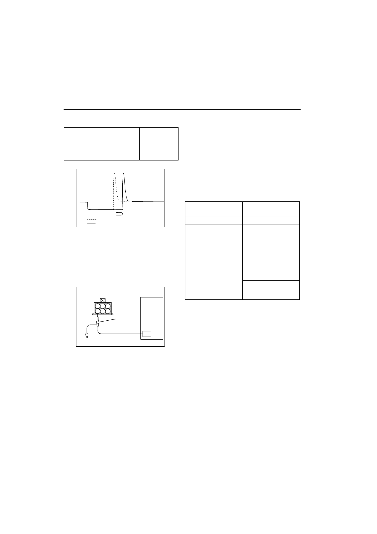
Wave Pattern Observation Points
Point A: Height of solenoid back electromotive force
Point B: Injector drive time
The injector drive time will be synchronized with the
MUT-II tester display.
When the engine is suddenly raced, the drive
time will be greatly extended at first, but the drive
time will soon match the engine speed.
IDLE SPEED CONTROL (ISC) SERVO
(STEPPER MOTOR)
Measurement Method
1. Disconnect the ISC servo connector, and connect
the special tool Test harness (MB991709) in
between.
2. Connect the oscilloscope special patterns pickup
to the ISC servo-side connector terminal No. 1,
No. 3, No. 4 and No. 6 respectively.
Alternate Method (Test harness not available)
1. Connect the oscilloscope special patterns pickup
to engine-ECU terminal No. 4, connection
terminal No. 5, connection terminal No. 17, and
connection terminal No. 18 respectively.
Standard Wave Pattern
Observation conditions
Contrast with standard wave
pattern
Probable
cause
Solenoid coil back electromotive
force is low or doesn’t appear at
all.
Short in the
injector solenoid
AKX01605AE
When idling
When racing
1 2 3
5
4
6
AK300344AB
Special
patterns
pickup
Oscilloscope
Function
Special patterns
Pattern height
High
Pattern selector
Display
Engine condition
When the engine coolant
temperature is 20
C or
below, turn the ignition
switch from LOCK (OFF)
position to ON (without
starting the engine).
While the engine is
idling, turn the A/C
switch to ON.
Immediately after
starting the warm
engine.