Mitsubishi Outlander (2003+). Manual - part 108
TROUBLESHOOTING
MULTIPORT FUEL INJECTION (MFI)
13A-295
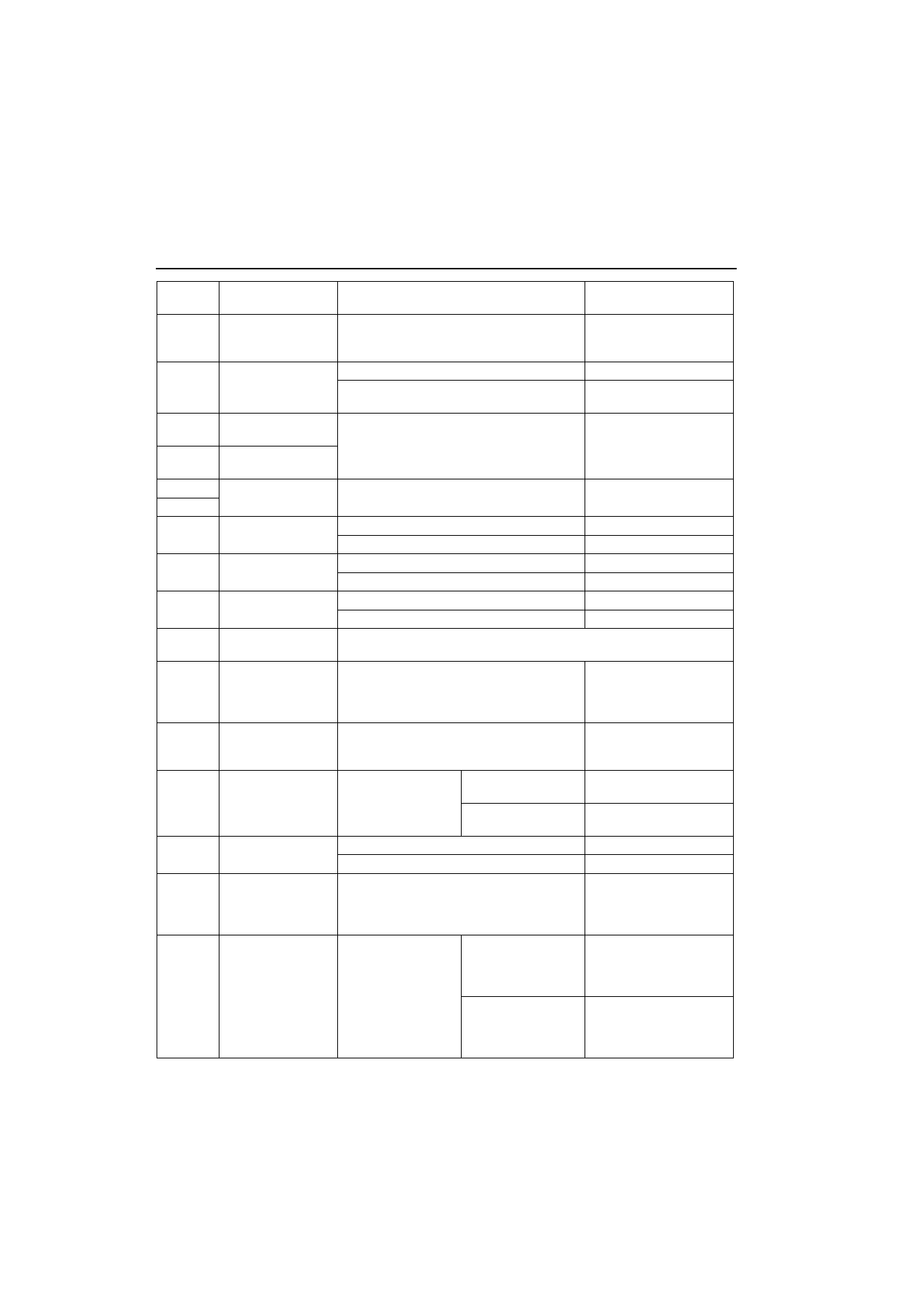
8
A/C relay
Engine: Idle speed
A/C switch: OFF
ON (A/C compressor
is operating)
System voltage or
Momentarily 6V or more
1 V or less
9
Purge control
solenoid valve
Ignition switch: "ON"
System voltage
Running at 3,500 r/min while engine is
warming up after having been started.
1 V or less
10
Ignition coil
-
No. 1,
No. 4
Engine r/min: 3,000 r/min
0.3
-
3.0 V
23
Ignition coil
-
No. 2,
No. 3
12
Power supply
Ignition switch: "ON"
System voltage
25
19
Air flow sensor reset
Signal
Engine: Idle speed
0
-
1 V
Engine r/min: 3,000 r/min
6
-
9 V
21
Fan controller
Radiator and condenser fan is not operating
0
-
0.3 V
Radiator and condenser fan is operating
0.7 V or more
22
Fuel pump relay
Ignition switch: ON
System voltage
Engine: Idle speed
1 V or less
24
A/C load signal
Refer to GROUP 55 - Troubleshooting (Inspection at the Automatic
compressor - ECU Terminal)
33
Alternator G terminal
Engine: Warm, idle (radiator fan: OFF)
Headlamp: OFF
ON
Stop lamp: OFF
ON
Rear defogger switch: OFF
ON
Voltage increases by 0.2
-
3.5 V
36
Engine warming
lamp
Ignition switch: "LOCK" (OFF)
"ON"
1 V or less
System
voltage (After several
seconds have elapsed)
37
Power steering fluid
pressure switch
Engine: Idling after
warming up
When steering wheel
is Stationary
System voltage
When steering wheel
is turned
1 V or less
38
Control relay (Power
supply)
Ignition switch: "LOCK" (OFF)
System voltage
Ignition switch: "ON"
1 V or less
41
Alternator FR
terminal
Engine: Warm, idle (radiator fan: OFF)
Headlamp: OFF
ON
Stop lamp: OFF
ON
Rear defogger switch: OFF
ON
Voltage decreases
42
A/C pressure sensor
Engine: Idling
A/C switch: ON
When A/C is "MAX,
COOL" condition
(when the load by
A/C is high)
2.2 V or more
When A/C is "MAX,
HOT" condition (when
the load by A/C is
low)
1.8 V or less
Terminal
No.
Check item
Check condition (Engine condition)
Normal condition