Mitsubishi Outlander (2003+). Manual - part 113


  Index      Mitsubishi     Mitsubishi Outlander - service repair manual 2003 year


Search            


Content   ..  111  112  113  114   ..


Mitsubishi Outlander (2003+). Manual - part 113


ON-VEHICLE SERVICE

MULTIPORT FUEL INJECTION (MFI)

13A-315

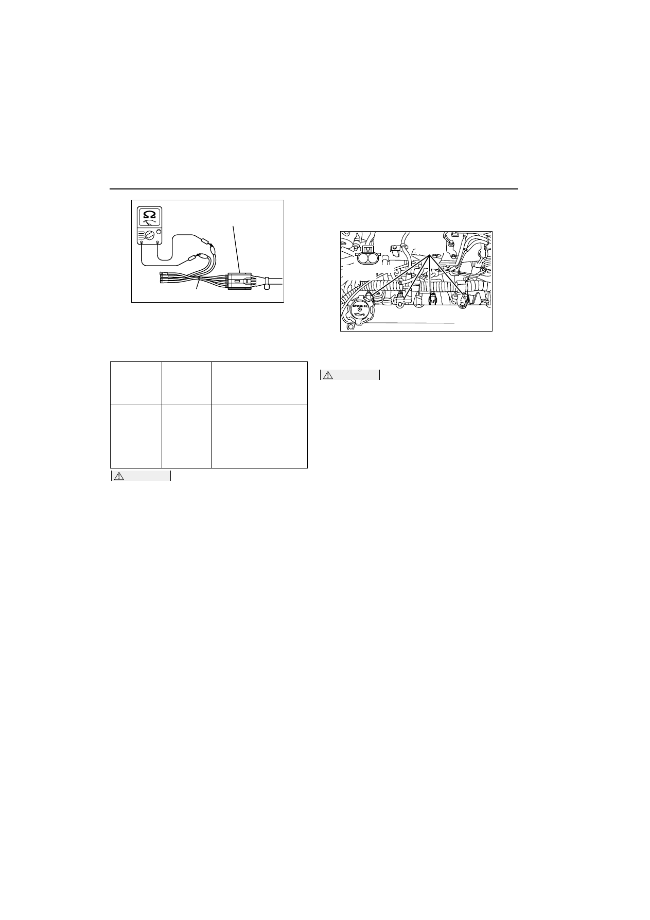
6. Connect a digital voltage meter between terminal 

No. 3 and No. 4.

7. While repeatedly racing the engine, measure the 

oxygen sensor output voltage.

Standard value:

CAUTION

œ

Be very careful when connecting the jumper 
wire; incorrect connection can damage the 
oxygen sensor.

œ

Be careful the heater is broken when voltage 
of beyond 8V is applied to the oxygen sensor 
heater.

NOTE: If the sufficiently high temperature (of 
approximate 400

•

C or more) is not reached 

although the oxygen sensor is normal, the output 
voltage would be possibly low although the rich 
air-fuel ratio. Therefore, if the output voltage is 
low, use a jumper wire to connect the terminal 
No.2 and the terminal No. 1 of the oxygen sensor 
with a (+) terminal and (-) terminal of 8 V power 
supply respectively, then check again.

8. If the sensor is defective, replace the oxygen 

sensor.

NOTE: For removal and installation of the oxygen 
sensor, refer to GROUP 15 

-

 Exhaust Pipe and 

Main Muffler 

3

15


.

INJECTOR CHECK

M1131005200327

Check the Operation Sound

1. Use a stethoscope to listen to the operation sound 

(clicking) of the injectors while the engine is idling 
or cranking.

CAUTION

Beware that the operation sounds of other injec-
tors can be heard even if the injector that is being 
inspected might not be operating.
2. Verify that the operation sound increases with the 

engine speed.

NOTE: If the operating sound cannot be heard, 
inspect the injector actuation circuit.

Measurement of Resistance between Ter-
minals

1. Disconnect the injector connector.
2. Measure the resistance between terminals.

Standard value: 10.5 

-

 13.5 

W

 (at 20

•

C)

3. Connect the injector connector.

Check the Injection Condition

1. Following the steps below, bleed out the residual 

pressure within the fuel pipe line to prevent flow of 
the fuel (Refer to 

3

13A


).

2. Remove the injector.
3. Assemble the following special tools as shown in 

Fig.

œ

Injector test set (MD998706)

œ

Injector test harness (MB991607)

œ

Injector test adaptor (MD998741)

œ

Clip (MB991608)

Engine

Oxygen 
sensor 
output 
voltage

Remarks

When 
racing the 
engine

0.6 

-

 1.0 V

If you make the air-fuel 
ratio rich by racing the 
engine repeatedly, a 
normal oxygen sensor 
will output a voltage of 
0.6 

-

 1.0 V.

AK000121

Oxygen sensor

MB991658

AC

AK300358

1 2

AB

Injector

Equipment side
connector

ON-VEHICLE SERVICE

MULTIPORT FUEL INJECTION (MFI)

13A-316

4. Connect the MUT-II to the diagnosis connector.
5. Turn the ignition switch to "ON" position (But do 

not start the engine).

6. Select "Item No. 07" from the MUT-II Actuator test 

to drive the fuel pump.

7. Activate the injector and check the atomized 

spray condition of the fuel.

The condition can be considered satisfactory 
unless it is extremely poor.

8. Stop the actuation of the injector, and check for 

leakage from the injector’s nozzle.

Standard value: 1 drop or less per minute

9. Activate the injector without activating the fuel 

pump; then, when the spray emission of fuel from 
the injector stops, disconnect the special tool and 
restore it to its original condition.

10.Disconnect the MUT-II.

IDLE SPEED CONTROL (ISC) SERVO 
(STEPPER MOTOR) CHECK

M1131005400417

Check the Operation Sound

1. Check that the engine coolant temperature is 

20

•

C or below.

NOTE: Disconnecting the engine coolant temper-
ature sensor connector and connecting the har-
ness-side of the connector to another engine 
coolant temperature sensor that is at 20

•

C or 

below is also okay.

2. Check that the operation sound of the stepper 

motor can be heard after the ignition is turned to 
the "ON" position (but without starting the engine).

3. If the operation sound cannot be heard, check the 

stepper motor’s activation circuit.

If the circuit is normal, it is probable that there is a 
malfunction of the stepper motor or of the engine-
ECU.

AK101794

High-pressure fuel hose

MD998741

MB991607

Clip (MB991608)

Injector

MD998706

Pressure regulator

Return hose

Battery

AD

AK101795

Return hose

Injector

AC

Battery

Mainhose

AK300359

1 2

3

4 5

6

AB

Equipment side
connector

Idle speed
control servo

ON-VEHICLE SERVICE

MULTIPORT FUEL INJECTION (MFI)

13A-317

Check the Coil Resistance

1. Disconnect the idle speed control servo 

connector.

2. Measure the resistance between terminal No. 2 

and either terminal No. 1 or terminal No. 3 of the 
connector at the idle speed control servo side.

Standard value: 28 

-

 33 

W

 (at 20

•

C)

3. Measure the resistance between terminal No. 5 

and either terminal No. 6 or terminal No. 4 of the 
connector at the idle speed control servo side.

Standard value: 28 

-

 33 

W

 (at 20

•

C)

Operation Check

1. Remove the throttle body.
2. Remove the stepper motor.
3. Connect the special tool Test harness 

(MB991709) to the idle speed control servo 
connector.

4. Connect the positive (+) terminal of a power 

supply (approximately 6 V) to the terminals No. 2 
and No. 5.

5. With the idle speed control servo as shown in the 

illustration, connect the negative (

-

) terminal of 

the power supply to each clip as described in the 
following steps, and check whether or not a 
vibrating feeling (a feeling of very slight vibration 
of the stepper motor) is generated as a result of 
the activation of the stepper motor.
(1) Connect the negative (

-

) terminal of the power 

supply to the terminal No. 1 and terminal No. 
4.

(2) Connect the negative (

-

) terminal of the power 

supply to the terminal No. 3 and terminal No. 
4.

(3) Connect the negative (

-

) terminal of the power 

supply to the terminal No. 3 and terminal No. 
6.

(4) Connect the negative (

-

) terminal of the power 

supply to the terminal No. 1 and terminal No. 
6.

(5) Connect the negative (

-

) terminal of the power 

supply to the terminal No. 1 and terminal No. 
4.

(6) Repeat the tests in sequence from (5) to (1).

6. If vibration is detected during the test, the stepper 

motor can be considered to be normal.

AKX01561

1 2 3
4 5 6

1 2 3
4 5 6

AE

AKX01626

INJECTOR

MULTIPORT FUEL INJECTION (MFI)

13A-318

INJECTOR

REMOVAL AND INSTALLATION

M1131007100649

REMOVAL SERVICE POINT

<<A>> FUEL DELIVERY PIPE AND FUEL INJEC-
TOR ASSEMBLY REMOVAL

CAUTION

Do not drop the injector.
Remove the fuel delivery pipe with the fuel injector 
assembly attached to it.

INSTALLATION SERVICE POINT

>>A<< FUEL INJECTOR ASSEMBLY/DELIVERY 
PIPE PRESSURE REGULATOR/FUEL HIGH-
PRESSURE HOSE INSTALLATION

CAUTION

Do not let the engine oil get into the delivery pipe 
will be damaged.
1. Apply a drop of new engine oil to the O-ring.

Pre-removal Operation

œ

Fuel Discharge Prevention (Refer to 

3

13A


).

œ

Air Cleaner Removal (Refer to GROUP 15, Air Cleaner 

3

15


).

Post-installation Operation

œ

Air Cleaner Installation (Refer to GROUP 15, Air Cleaner 

3

15


).

œ

Fuel Leakage Inspection.

AC300484 AB

8

5.0 ± 1.0 N·m

8.9 ± 1.9 N·m

11 ± 1 N·m

1

2

3

4

5

6

6,10

7

7,11

16

10

11

19

19

9

13

15

N

N

17

18

18

15

N

N

16

Engine Oil

14

12

Removal steps

1.

PCV hose connection

2.

Injector connector

3.

Idle speed control servo connector

4.

Throttle position sensor connector

5.

Emission control equipment hose 
connector

>>A<<

6.

Fuel high-pressure hose 
connection

7.

O-ring

8.

Fuel return hose connection

9.

Fuel hose

>>A<<

10. Delivery pipe pressure regulator
11. O-ring

<<A>>

12. Fuel delivery pipe and fuel injector 

assembly 

13. Insulators

>>A<<

14. Fuel injector assembly
15. O-ring
16. Fuel injector sheets
17. Insulators
18

Fuel injectors

19. Fuel delivery pipe


Content   ..  111  112  113  114   ..