Mitsubishi Outlander (2003+). Manual - part 84


  Index      Mitsubishi     Mitsubishi Outlander - service repair manual 2003 year


Search            


Content   ..  82  83  84  85   ..


Mitsubishi Outlander (2003+). Manual - part 84


TROUBLESHOOTING

MULTIPORT FUEL INJECTION (MFI)

13A-199

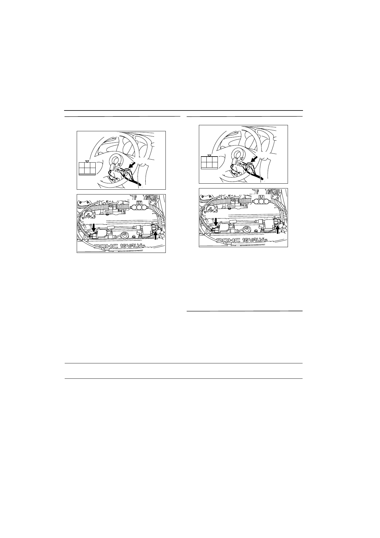
STEP 14: Connector check: C-303 ignition switch 
connector

Q: Is the check result normal?

YES : 

Check intermediate connectors A-14, C-

116, C-203 and C-205, and repair if 
necessary. Check and repair harness 
between C-303 (terminal No. 2) ignition 
switch connector and (terminal No. 1) 
affected cylinders ignition coil connector.

œ

Check power supply line for 
open/short circuit.

NO : 

Repair.

STEP 15: Check ignition coil spark.

Q: Is the check result normal?

YES : 

Go to Step 16 .

NO : 

Check intermediate connectors A-14, C-116, 

C-203 and C-205, and repair if necessary. 
Check and repair harness between C-303 
(terminal No. 2) ignition switch connector 
and (terminal No. 1) affected cylinder’s 
ignition coil connector.

œ

Check power supply line for damage.

STEP 16: Replace engine-ECU

œ

After replacing the engine-ECU, re-check the 
trouble symptoms.

Q: Does trouble symptom persist? 

YES : 

Check for foreign matters (water, kerosene, 

etc.) in fuel and replace if necessary. 

NO : 

Check end.

Inspection Procedure 7: Starting Impossible (Initial Combustion But no Complete Combustion), 
Improper Starting (Long time to Start)

COMMENT ON TROUBLE SYMPTOM

œ

Failure is possibly caused by poor ignition, incor-
rect air-fuel ratio at cranking, improper fuel pres-
sure or other faults.

PROBABLE CAUSE

œ

Failed battery 

œ

Failed ignition system 

œ

Failed fuel system 

œ

Air-fuel ratio control

œ

Failed idle speed control system

œ

Failed intake system 

œ

Failed exhaust gas cleaning system

œ

Throttle valve fouled around 

œ

Timing belt not in place 

œ

Compression pressure improper 

œ

Failed engine-ECU

1

2

3

4

5

6

AK300304

CONNECTOR: C-303

C-303

Harness side
connector

AB

AK300308

1

2

3

AB

Harness side 
connector

B-111 (GR)

B-110 (GR)

Connector: B-110, B-111

1

2

3

4

5

6

AK300304

CONNECTOR: C-303

C-303

Harness side
connector

AB

AK300308

1

2

3

AB

Harness side 
connector

B-111 (GR)

B-110 (GR)

Connector: B-110, B-111

TROUBLESHOOTING

MULTIPORT FUEL INJECTION (MFI)

13A-200

DIAGNOSIS PROCEDURE

STEP 1: Check battery condition.

Q: Have the battery terminal been disconnected? 

YES : 

After warm-up engine, idle for about 10 

minutes.

NO : 

Go to Step 2 .

STEP 2: Check battery voltage.

œ

Measure battery voltage at cranking.

OK: 8 V or higher 

Q: Is the check result normal?

YES : 

Go to Step 3 .

NO : 

Check battery (Refer to GROUP 54 

-


Battery 

-

 On-vehicle Service 

-

 Battery Test 

3

54A


).

STEP 3: MUT-II self-diag code

Q: Diagnosis code set?

YES : 

Inspection chart for diagnosis codes (Refer 

to 

3

13A


)

NO : 

Go to Step 4 .

STEP 4: MUT-II data list

œ

Refer to Data list reference table 

3

13A


.

a. Item 13: Intake air temperature sensor 
b. Item 21: Engine coolant temperature sensor 

c. Item 25: Barometric pressure sensor 

Q: Are the check results normal?

YES : 

Go to Step 5 .

NO : 

Perform the diagnosis code classified check 
procedure for the sensor that has shown an 
abnormal data value (Refer to Inspection 
Chart for Diagnosis Code

3

13A


).

STEP 5: Check start ability.

œ

With depressing the accelerator pedal slightly, 
and start the engine. 

Q: Is the start ability good?

YES : 

Go to Step 6 .

NO : 

Go to Step 7 .

STEP 6: Check idle speed control servo for 
operating sound.

œ

Check idle speed control servo for operating 
sound (Refer to 

3

13A


).

Q: Is the check result normal?

YES : 

Clean throttle body (throttle valve portion) 

(Refer to 

3

13A


).

NO : 

Check idle speed control servo system 
(Refer to Code No. P0505 

3

13A


).

STEP 7: MUT-II actuator test

œ

Item 07: Fuel pump 

OK: Operating sound of fuel pump can be 
heard.

Q: Is the check result normal?

YES : 

Go to Step 8 .

NO : 

Check fuel pump system (Refer to 
Inspection Procedure 24 

3

13A


).

STEP 8: Check air intake from intake hose and 
inlet manifold.

Q: Is the check result normal?

YES : 

Go to Step 9 .

NO : 

Repair.

STEP 9: Check injector for operating sound.

œ

Check injector for operating sound at engine 
cranking (Refer to 

3

13A


).

Q: Can operating sound be heard?

YES : 

Go to Step 10 .

NO : 

Check the injector system of the defective 

cylinder.

(Refer to Code No. P0201: No.1 injector system 

3

13A


.) 

(Refer to Code No. P0202: No.2 injector system 

3

13A


.) 

(Refer to Code No. P0203: No.3 injector system 

3

13A


.) 

(Refer to Code No. P0204: No.4 injector system 

3

13A


.) 

STEP 10. Check timing marks of timing belt.

Q: Is the check result normal?

YES : 

Go to Step 11 .

NO : 

Align timing marks.

TROUBLESHOOTING

MULTIPORT FUEL INJECTION (MFI)

13A-201

STEP 11: Measure voltage at C-134 engine-ECU 
connector.

œ

Measure engine-ECU terminal voltage. 

œ

Ignition switch: ON

œ

Voltage between terminal No. 13 and earth, also 
between terminal No. 26 and earth.

OK: 0.5 V or less 

Q: Is the check result normal?

YES : 

Go to Step 13 .

NO : 

Go to Step 12 .

STEP 12: Connector check: C-134 engine-ECU 
connector

Q: Is the check result normal?

YES : 

Check and repair harness between C-134 

(terminal No. 13 and No. 26) engine-ECU 
connector and body earth.

œ

Check earthing line for open circuit 
and damage.

NO : 

Repair.

STEP 13: Connector check: B110 and B-111 
ignition coil connectors

Q: Is the check result normal?

YES : 

Go to Step 14 .

NO : 

Repair.

STEP 14: Check ignition coil spark.

Q: Is the check result normal?

YES : 

Go to Step 19 .

NO : 

Go to Step 15 .

STEP 15: Check spark plug.

Q: Is the check result normal?

YES : 

Go to Step 16 .

NO : 

Replace spark plug.

STEP 16: Check spark plug cable itself. 

œ

Check spark plug cable itself (Refer to GROUP 
16 

-

 Ignition System 

-

 On-vehicle Service 

3

16


).

Q: Is the check result normal?

YES : 

Go to Step 17 .

NO : 

Replace spark plug cable.

STEP 17: Check ignition coil itself.

œ

Check ignition coil itself (Refer to GROUP 16 

-


Ignition System 

-

 On-vehicle Servic

3

16


).

Q: Is the check result normal?

YES : 

Go to Step 18 .

NO : 

Replace ignition coil.

AK300257

1

14

4

19

5

22

6

17

8

15

9

18

7

20

16

2

13 12

23

24

25

26

21

3

10

11

AB

CONNECTOR: C-134

C-134

Harness side connector

AK300257

1

14

4

19

5

22

6

17

8

15

9

18

7

20

16

2

13 12

23

24

25

26

21

3

10

11

AB

CONNECTOR: C-134

C-134

Harness side connector

AK300308

1

2

3

AB

Harness side 
connector

B-111 (GR)

B-110 (GR)

Connector: B-110, B-111

TROUBLESHOOTING

MULTIPORT FUEL INJECTION (MFI)

13A-202

STEP 18: Check harness between terminal No. 2 
of each cylinder’s ignition coil connector and 
vehicle body earth.

œ

Check earthing line for open circuit and damage.

Q: Is the check result normal?

YES : 

Check and repair harness between terminal 

No. 3 of each cylinder’s ignition coil 
connector and C-134 engine-ECU 
connector. 

œ

Check signal line for open/short 
circuit and damage. 

NO : 

Repair.

STEP 19: Check spray condition of injector.

œ

Check each injector for spray condition (Refer to 

3

13A


).

Q: Is the check result normal?

YES : 

Go to Step 20 .

NO : 

Replace injector.

STEP 20: Check compression pressure.

œ

Check compression pressure (Refer to GROUP 
11A 

-

 On-vehicle Service 

3

11A


).

Q: Is the check result normal?

YES : 

Go to Step 21 .

NO : 

Repair.

STEP 21: Check EGR control solenoid valve 
itself.

œ

Check EGR control solenoid valve itself [Refer to 
GROUP 17 

-

 Emission Control System 

-


Exhaust Gas Recirculation (EGR) System 

3

17


].

Q: Is the check result normal?

YES : 

Go to Step 22 .

NO : 

Replace EGR control solenoid valve.

STEP 22: Check EGR valve itself.

œ

Check EGR valve itself [Refer to GROUP 17 

-


Emission Control System 

-

 Exhaust Gas Recir-

culation (EGR) System 

3

17


].

Q: Is the check result normal?

YES : 

Go to Step 23 .

NO : 

Replace EGR valve.

STEP 23: Replace engine-ECU.

œ

After replacing the engine-ECU, re-check the 
trouble symptoms. 

Q: Does trouble symptom persist?

YES : 

Check for foreign matters (water, kerosene, 

etc.) in fuel and replace if necessary. 

NO : 

Check end.

Inspection Procedure 8: Unstable idling (Rough idling, hunting), Improper idling speed (Too high or 
too low), Engine stalls during idling (Die out)

COMMENT ON TROUBLE SYMPTOM

œ

Probable causes can be widely found in ignition 
system, air-fuel ratio control system, idle speed 
control system, fuel system, etc. A sudden 
engine stall is possibly caused by poor connector 
contact.

PROBABLE CAUSE

œ

Failed ignition system

œ

Failed fuel system 

œ

Failed air-fuel ratio control system 

œ

Failed idle speed control system

œ

Failed intake/exhaust system

AK300308

1

2

3

AB

Harness side 
connector

B-111 (GR)

B-110 (GR)

Connector: B-110, B-111

AK300257

1

14

4

19

5

22

6

17

8

15

9

18

7

20

16

2

13 12

23

24

25

26

21

3

10

11

AB

CONNECTOR: C-134

C-134

Harness side connector


Content   ..  82  83  84  85   ..