Mitsubishi Outlander (2003+). Manual - part 21


  Index      Mitsubishi     Mitsubishi Outlander - service repair manual 2003 year


Search            


Content   ..  19  20  21  22   ..


Mitsubishi Outlander (2003+). Manual - part 21


ON-VEHICLE SERVICE

ENGINE MECHANICAL <4G69>

11C-11

VALVE CLEARANCE CHECK AND 
ADJUSTMENT

M1111001500131

1. Start the engine and allow it to warm up until the 

engine coolant temperature reaches 80 

 95

°

C.

2. Turn the ignition switch to the "LOCK" (OFF) 

position.

3. Remove all ignition coils.
4. Remove all spark plugs from the cylinder head for 

easy inspection.

5. Remove the rocker cover.
6. Turn the crankshaft clockwise until the notch on 

the pulley is lined up with the "T" mark on the 
timing indicator.

7. Move the rocker arms on the No.1 and No.4 

cylinders up and down by hand to determine 
which cylinder has its piston at the top dead 
center on the compression stroke. If both intake 
and exhaust valve rocker arms have a valve lash, 
the piston in the cylinder corresponding to these 
rocker arms is at the top dead center on the 
compression stroke.

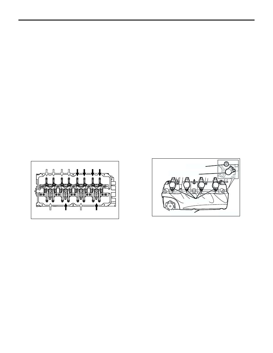
8. Valve clearance inspection and adjustment can be 

performed on rocker arms indicated by white 
arrow mark when the No.1 cylinder piston is at the 
top dead centre on the compression stroke, and 
on rocker arms indicated by black arrow mark 
when the No.4 cylinder piston is at the top dead 
centre on the compression stroke.

9. Measure the valve clearance.

If the valve clearance is not as specified, loosen 
the rocker arm lock nut and adjust the clearance 
using a thickness gauge while turning the 
adjusting screw.

Standard value (hot engine):

Intake valve: 0.20 mm
Exhaust valve: 0.30 mm

10.While holding the adjusting screw with a 

screwdriver to prevent it from turning, tighten the 
lock nut to the specified torque.

Tightening torque: 9 

±

 1 N

m

11.Turn the crankshaft through 360

°

 to line up the 

notch on the crankshaft pulley with the "T" mark 
on the timing indicator.

12.Repeat steps (9) and (10) on other valves for 

clearance adjustment.

13.Install the rocker cover.
14.Install the spark plugs and tighten to the specified 

torque.

Tightening torque: 25 

±

 4 N

m

15.Install the ignition coils.

ROCKER ARM PISTON OPERATION 
CHECK

M1111051000023

1. Remove all of the ignition coils.
2. Remove the rocker cover.
3. Remove the oil control valve.
4. Remove the taper plug.
5. Turn the crankshaft clockwise until the notch on 

the crankshaft pulley is lined up with "T" mark on 
the lower cover of timing belt.

6. Move the rocker arms on the No.1 and No.4 

cylinders up and down by hand to determine 
which cylinder has its piston at the top dead 
centre on the compression stroke. 

AK303689 AB

Exhaust valve side

No. 1

No. 2

No. 3

No. 4

Intake valve side

AK304505AB

Taper plug

Oil  control valve

Ignition coils

Rocker cover

ON-VEHICLE SERVICE

ENGINE MECHANICAL <4G69>

11C-12

NOTE: 

The rocker arm piston operation check can be 
performed on rocker arms indicated by white arrow 
mark when the No.1 cylinder piston is at the top dead 
centre on the compression stroke, and on rocker 
arms indicated by black arrow mark when the No.4 
cylinder piston is at the top dead centre on the 
compression stroke.

7. While shutting up the oil passage hole at the 

depth of the oil control valve's installation hole by 
finger not to leak air, blow compression air into the 
taper plug's installation hole by air blowgun. At 
this time, confirm that the rocker arm piston can 
operate.

NOTE: To fully confirm the check, prevent the 
compression air from leaking as much as possible by 
installing the O-ring to the end of air blowgun.
8. Turn the crankshaft clockwise until the notch on 

the crankshaft pulley is lined up with "T" mark on 
the lower cover of timing belt.

9. Confirm the rest of the rocker arm pistons under 

the procedure 7.

10.When the rocker arm piston does not operate, 

replace the rocker arm assy.

11.Apply sealant to threaded portion.

Specified sealant: LOCTITE203MP

CAUTION

Do not start the engine within one hour after the 
engine taper plug has been installed.
12.Install the taper plug and tighten to the specified 

torque.

Tightening torque: 10 

±

 2 N

m

13.Install the oil control valve. (Refer to Camshaft 

and Valve Stem Seal 

 Removal and Installation 

P.11C-18

.)

14.Install all of the ignition coils.
15.Install the rocker cover.

AK303689 AC

Exhaust valve side

No. 1

No. 2

No. 3

No. 4

Intake valve side

AK302684AC

Rocker arm
piston

Blow
compression
air

Oil passage

Rocker arm

ON-VEHICLE SERVICE

ENGINE MECHANICAL <4G69>

11C-13

IGNITION TIMING CHECK

M1111001700607

1. Before inspection, set the vehicle to the 

pre-inspection condition.

2. Turn the ignition switch to the "LOCK" (OFF) 

position and then connect the MUT-II/III to the 
diagnosis connector.

3. Connect a timing light.
4. Start the engine and let it run at idle.
5. Use the MUT-II/III to measure engine idle speed 

and check that it is within the standard value.

Standard value

: 680 

±

 100 r/min <M/T>

: 750 

±

 100 r/min <A/T>

6. Select No. 17 of the MUT-II/III Actuator test.
7. Check that basic ignition timing is within the 

standard value.

Standard value: 5

°

 BTDC 

±

 3

°

8. If the basic ignition timing is outside the standard 

value, inspect the MPI system (Refer to 

P.13B-20

GROUP 13B 

 Troubleshooting 

 Inspection chart 

for diagnosis code).

CAUTION

If the test is not cancelled, a forced driving will 
continue for 27 minutes. Driving under this 
condition may damage the engine.
9. Press the MUT-II/III clear key (Select a forced 

driving cancel mode) to release the Actuator test.

10.Check that ignition timing is at the standard value.

Standard value: approximately 10

°

 BTDC

NOTE: 

.

The ignition timing may fluctuate within 

±

 7

°


BTDC. This is normal.

In higher altitude, the ignition timing is more 
advanced than the standard value by 
approximately 5

°

.

11.Remove the timing light.
12.Turn the ignition switch to the "LOCK" (OFF) 

position and then remove the MUT-II/III.

AK303691AF

MB991502

16 PIN

AK303690AB

MB991911

16-PIN

MB991827

MB991824 

ON-VEHICLE SERVICE

ENGINE MECHANICAL <4G69>

11C-14

IDLE SPEED CHECK 

M1111003500654

1. Before inspection, set the vehicle to the 

pre-inspection condition.

2. Turn the ignition switch to the "LOCK" (OFF) 

position and then connect the MUT-II/III to the 
diagnosis connector.

3. Connect a timing light.
4. Start the engine and let it run at idle.
5. Check that ignition timing is at the standard value.

Standard value: approximately 10

°

 BTDC

6. Check the idle speed.

Standard value

: 680 

±

 100 r/min <M/T>

: 750 

±

 100 r/min <A/T>

NOTE: 

.

The idle speed is controlled automatically by 
the idle speed control system.

When using the MUT-II/III, select item No. 22 
and take a reading of the idle speed.

7. If the idle speed is outside the standard value, 

inspect the MPI system (Refer to 

P.13B-20

GROUP 13B 

 Troubleshooting 

 Inspection chart 

for diagnosis code).

8. Turn the ignition switch to the "LOCK" (OFF) 

position and then remove the MUT-II/III.

IDLE MIXTURE CHECK

M1111002100426

1. Before inspection, set the vehicle to the 

pre-inspection condition.

2. Turn the ignition switch to the "LOCK" (OFF) 

position and then connect the MUT-II/III to the 
diagnosis connector.

3. Connect a timing light.
4. Start the engine and let it run at idle.
5. Check that ignition timing is at the standard value.

Standard value: approximately 10

°

 BTDC

6. Run the engine at 2,500 r/min for 2 minutes.
7. Set the CO, HC tester.

AK303691AF

MB991502

16 PIN

AK303690AB

MB991911

16-PIN

MB991827

MB991824 

AK303691AF

MB991502

16 PIN

AK303690AB

MB991911

16-PIN

MB991827

MB991824 


Content   ..  19  20  21  22   ..