Mitsubishi Montero Sport (2004+). Manual - part 793


  Index      Mitsubishi     Mitsubishi Montero Sport - service repair manual 2004 year


Search            


Content   ..  791  792  793  794   ..


Mitsubishi Montero Sport (2004+). Manual - part 793


ANTI-LOCK BRAKING SYSTEM (ABS) DIAGNOSIS

TSB Revision

ANTI-LOCK BRAKING SYSTEM (ABS) <RWD>

35B-53

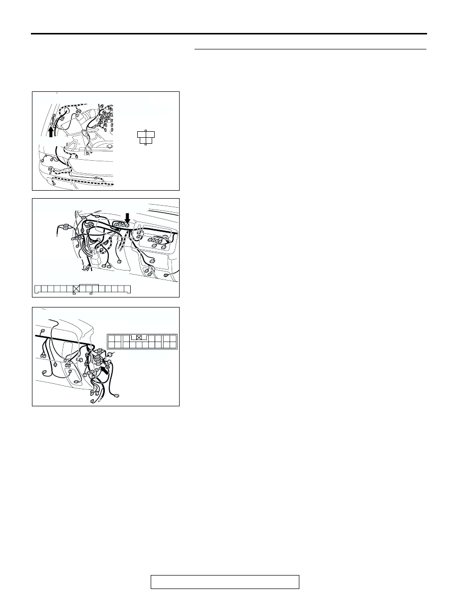
STEP 2. Check harness connectors A-35, C-05 and C-17 for 
loose, corroded or damaged terminals, or terminals 
pushed back in the connector.

Refer to GROUP 00E, Harness Connector Inspection 

P.00E-2

Q: Are the connectors and terminals in good condition?

YES : Go to Step 3.
NO :  Repair it and then go to Step 7.

AC201944

CONNECTOR : A-35

A-35(B)

A-35 HARNESS 
CONNECTOR:
COMPONENT SIDE

AC

1

3

2

4

AC201948

CONNECTOR : C-05

AC

3 2 1

4

5

7 6

8

9

11

12

10

13

14

C-05 HARNESS CONNECTOR:
COMPONENT SIDE

C-05

AC201950

CONNECTOR : C-17

C-17

AB

17

7

15

5

16

6

12 13

10

3

11

14

4

8

1

9

2

ANTI-LOCK BRAKING SYSTEM (ABS) DIAGNOSIS

TSB Revision

ANTI-LOCK BRAKING SYSTEM (ABS) <RWD>

35B-54

STEP 3. Check the harness wire between ABS relay 
connector A-35 (terminal No. 3) and combination meter 
connector C-05 (terminal No.10).

Q: Is the harness wire between ABS relay connector A-35 

(terminal No. 3) and combination meter connector C-05 
(terminal No.10) damaged?
YES : 
Repair it and then go to Step 7.
NO :  Replace the combination meter (printed circuit board) 

and then go to Step 7.

STEP 4. Check the ABS relay.

(1) Remove the ABS relay.
(2) Check for continuity between terminals 3 

− 4 when battery 

voltage is applied between terminals 1 

− 2.

Q: Is the ABS relay in good condition?

YES : Go to Step 5.
NO :  Replace the ABS relay. Then go to Step 7.

AC201944

CONNECTOR : A-35

A-35(B)

A-35 HARNESS 
CONNECTOR:
COMPONENT SIDE

AC

1

3

2

4

AC201948

CONNECTOR : C-05

AC

3 2 1

4

5

7 6

8

9

11

12

10

13

14

C-05 HARNESS CONNECTOR:
COMPONENT SIDE

C-05

BATTERY 
VOLTAGE

TESTER 
CONNECTION

SPECIFIED 
CONDITION

Not applied

− 4

Less than 2 ohms

• Connect 

terminal 2 to the 
positive battery 
terminal

• Connect 

terminal 1 to the 
negative battery 
terminal

− 4

Open circuit

AC004866

ANTI-LOCK BRAKING SYSTEM (ABS) DIAGNOSIS

TSB Revision

ANTI-LOCK BRAKING SYSTEM (ABS) <RWD>

35B-55

STEP 5. Check ABS relay connector A-35 and ABS-ECU 
connector A-85 for loose, corroded or damaged terminals, 
or terminals pushed back in the connector.

Refer to GROUP 00E, Harness Connector Inspection 

P.00E-2

Q: Are the connectors and terminals in good condition?

YES : Go to Step 6.
NO :  Repair or replace it. Then go to Step 7.

STEP 6. Check the harness wire between ABS relay 
connector A-35 (terminal No.1) and ABS-ECU connector 
A-85 (terminal No.16).

Q: Is the harness wire between ABS relay connector A-35 

(terminal No.1) and ABS-ECU connector A-85 (terminal 
No.16) damaged?
YES : 
Repair it and then go to Step 7.
NO :  Replace the hydraulic unit (integrated with ABS-ECU) 

and then go to Step 7.

AC201955

A-85(B)

A-35(B)

CONNECTORS :A-35, A-85

AC

A-85 HARNESS CONNECTOR:
COMPONENT SIDE

18

12 11

20 19

10

3 2 1

13

14

22

23

17 16

25 24

15

8 7 6 5 4

21

9

26

A-35 HARNESS CONNECTOR:
COMPONENT SIDE

1

3

2

4

AC201955

A-85(B)

A-35(B)

CONNECTORS :A-35, A-85

AC

A-85 HARNESS CONNECTOR:
COMPONENT SIDE

18

12 11

20 19

10

3 2 1

13

14

22

23

17 16

25 24

15

8 7 6 5 4

21

9

26

A-35 HARNESS CONNECTOR:
COMPONENT SIDE

1

3

2

4

ANTI-LOCK BRAKING SYSTEM (ABS) DIAGNOSIS

TSB Revision

ANTI-LOCK BRAKING SYSTEM (ABS) <RWD>

35B-56

STEP 7. Retest the system.
Q: Does the ABS warning light turn off 3 seconds after 

start-up?
YES : 
The procedure is complete.
NO :  Return to Step 1.

INSPECTION PROCEDURE 4: Brake Operation is Abnormal.

.

TECHNICAL DESCRIPTION (COMMENT)
The cause depends on driving and road surface con-
ditions, so diagnosis may be difficult. However, if no 
diagnostic trouble code is displayed, carry out the fol-
lowing inspection.

.

TROUBLESHOOTING HINTS
The most likely cause for this condition:

• Malfunction of the hydraulic unit

.

DIAGNOSIS

Check the hydraulic unit.

• Refer to 

P.35B-63

. If the hydraulic unit is malfunctioning, 

replace it. Then check that the malfunction symptom is elim-
inated.

DATA LIST REFERENCE TABLE

M1352011500649

The following items can be read by the scan tool from the ABS-ECU input data.

1. When the system is normal

2. When the ABS-ECU shuts off the ABS operation.
When the diagnostic trouble system stops the ABS-ECU, the scan tool display data will be unreliable.

MUT-III 
SCAN TOOL 
DISPLAY

ITEM 
NO.

INSPECTION ITEM

INSPECTION REQUIREMENT

NORMAL VALUE

BATT. 
VOLTAGE

16

ABS-ECU power supply 
voltage

Ignition switch power supply 
voltage and valve monitor voltage

− 16 V

FL SNSR

12

Front left wheel speed 
sensor

Drive the vehicle

Vehicle speeds 
displayed on the 
speedometer and 
scan tool are identical.

FR SNSR

11

Front right wheel speed 
sensor

RL SNSR

14

Rear left wheel speed 
sensor

RR SNSR

13

Rear right wheel speed 
sensor

STOPLIGHT 
SW

33

Stoplight switch

Depress the brake pedal.

ON

Release the brake pedal.

OFF


Content   ..  791  792  793  794   ..