Mitsubishi Montero Sport (2004+). Manual - part 791


  Index      Mitsubishi     Mitsubishi Montero Sport - service repair manual 2004 year


Search            


Content   ..  789  790  791  792   ..


Mitsubishi Montero Sport (2004+). Manual - part 791


ANTI-LOCK BRAKING SYSTEM (ABS) DIAGNOSIS

TSB Revision

ANTI-LOCK BRAKING SYSTEM (ABS) <RWD>

35B-45

.

DIAGNOSIS

Required Special Tool:

• MB991223: Harness Set

.

STEP 1. Check the ABS warning light circuit at ABS-ECU 
connector A-85.

(1) Disconnect ABS-ECU connector A-85.
(2) Turn the ignition switch to the "ON" position.
Q: Does the ABS warning light illuminate?

YES : Replace the hydraulic unit (integrated with ABS-ECU) 

and then go to Step 15.

NO :  Go to Step 2.

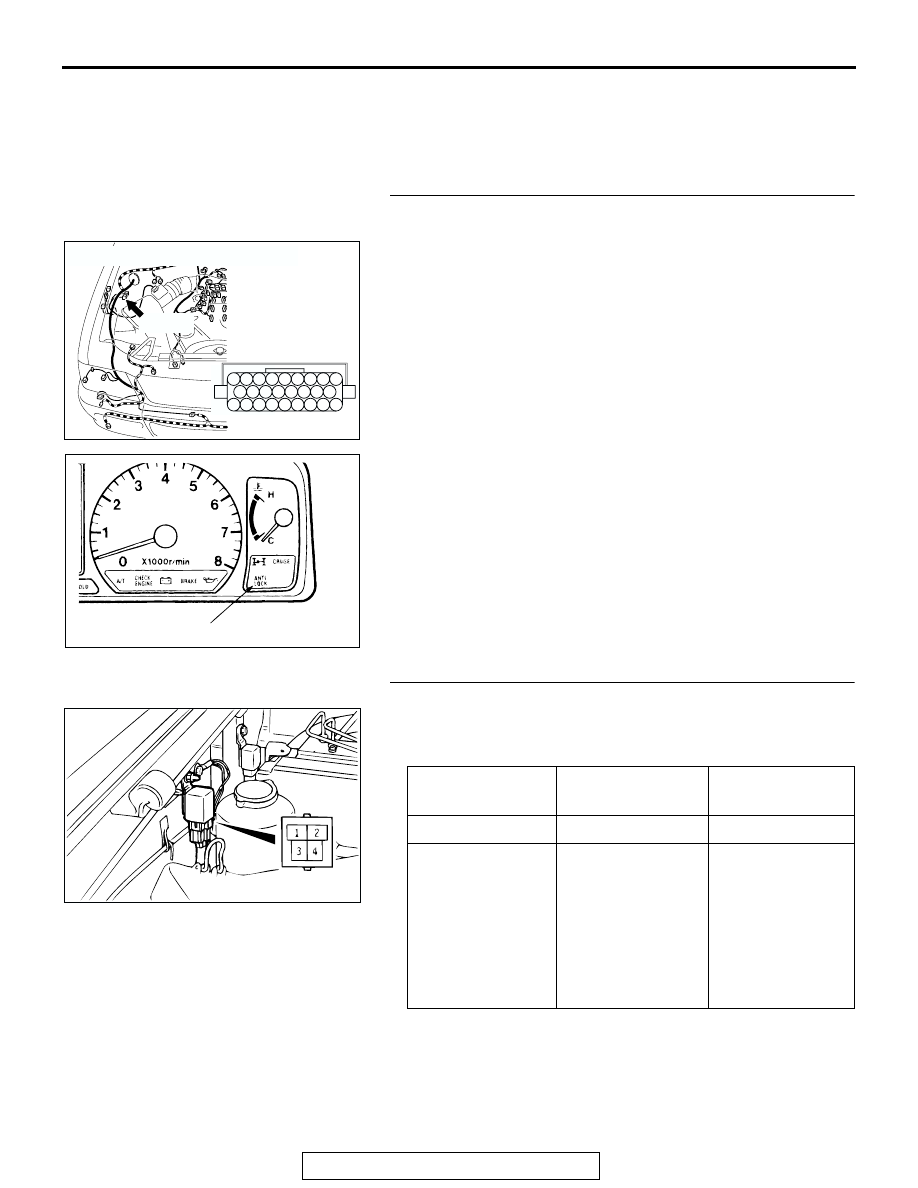
STEP 2. Check the ABS relay.

(1) Remove the ABS relay.
(2) Check for continuity between terminals 3 

− 4 when battery 

voltage is applied between terminals 1 

− 2.

Q: Is the ABS relay in good condition?

YES : Go to Step 3.
NO :  Replace the ABS relay. Then go to Step 15.

AC201944

CONNECTOR : A-85 

A-85(B)

A-85 HARNESS 
CONNECTOR:
COMPONENT SIDE

AD

18

12 11

20 19

10

3 2 1

13

14

22

23

17 16

25 24

15

8 7 6 5 4

21

9

26

AC004503 AC

ABS WARNING LIGHT

BATTERY 
VOLTAGE

TESTER 
CONNECTION

SPECIFIED 
CONDITION

Not applied

− 4

Less than 2 ohms

• Connect 

terminal 2 to the 
positive battery 
terminal

• Connect 

terminal 1 to the 
negative battery 
terminal

− 4

Open circuit

AC004866

ANTI-LOCK BRAKING SYSTEM (ABS) DIAGNOSIS

TSB Revision

ANTI-LOCK BRAKING SYSTEM (ABS) <RWD>

35B-46

STEP 3. Check the ABS warning light circuit at ABS relay 
connector A-35. 

(1) Disconnect ABS relay connector A-35.
(2) Ground terminal 3 of the ABS relay harness side connector.
(3) Turn the ignition switch to the "ON" position, and then ABS 

warning light should illuminate.

Q: Does the ABS warning light illuminate?

YES : Go to Step 11.
NO :  Go to Step 4.

STEP 4. Check the ABS warning light bulb.
(1) Remove the combination meter (Refer to GROUP 54A, 

Combination Mete

P.54-121

).

(2) Check the ABS warning light bulb.
Q: Is the bulb burned out?

YES : Replace the bulb and then go to Step 15.
NO :  Go to Step 5.

STEP 5. Measure the combination meter for continuity.

(1) Remove the combination meter.
(2) Remove the ABS warning light bulb. Then measure the 

resistance between the bulb terminals.

(3) Install the ABS warning light bulb to the combination meter, 

and then measure the resistance between connector C-04 
terminal 24 and connector C-05 terminal 10. The resistance 
reading at this time should be much the same as the 
resistance measured at step (2).

Q: Are the two resistance values extremely different each 

other?
YES : 
Replace the combination meter (printed circuit board) 

and then go to Step 15.

NO :  Go to Step 6.

STEP 6. Measure the combination meter power supply 
circuit.

(1) Disconnect connector C-04, and check at the harness side.
(2) Turn the ignition switch to the "ON" position.

(3) Measure the voltage between terminal 24 and ground. It 

should measure approximately 12 volts (battery positive 
voltage.)

Q: Is battery positive voltage (approximately 12 volts) 

present?
YES : 
Go to Step 9.
NO :  Go to Step 7.

AC309423AB

A-35 ABS RELAY CONNECTOR:
HARNESS SIDE

AC005098AD

C-04

C-05

C-04, C-05 COMBINATION 
METER CONNECTOR:

AC202699

21

23

24

27 26 25

22

28

30

31

29

32

AB

C-04 HARNESS CONNECTOR:
COMPONENT SIDE

ANTI-LOCK BRAKING SYSTEM (ABS) DIAGNOSIS

TSB Revision

ANTI-LOCK BRAKING SYSTEM (ABS) <RWD>

35B-47

STEP 7. Check connectors C-04, D-06 and D-08 for loose, 
corroded or damaged terminals, or terminals pushed back 
in the connector.

Check connectors C-04, D-06 and D-08. (Refer to GROUP 
00E, Harness Connector Inspection 

P.00E-2

.)

Q: Are the connectors and terminals in good condition?

YES : Go to Step 8.
NO :  Repair it and then go to Step 15.

STEP 8. Check for continuity between the ignition switch 
(IG1) and the combination meter connector C-04 (terminal 
No. 24).

Q: Is there any continuity (less than 2 ohms) between the 

ignition switch (IG1) and combination meter connector 
C-04 (terminal No. 24)?
YES : 
Go to Step 15.
NO :  Repair the harness wire and then go to Step 15.

AC201897

21

23

24

27 26 25

22

28

30

31

29

32

CONNECTOR: C-04

AB

C-04: HARNESS SIDE 
CONNECTOR

C-04

AC201951

CONNECTOR : D-06

D-06 HARNESS CONNECTOR:
COMPONENT SIDE

AC

1
8

3

4

5

7 6

10

15

16

14

12

13

11

9

2

AC201952

CONNECTOR : D-08

D-08 HARNESS CONNECTOR:
COMPONENT SIDE

AB

M

3

1

4

2

AC201897

21

23

24

27 26 25

22

28

30

31

29

32

CONNECTOR: C-04

AB

C-04: HARNESS SIDE 
CONNECTOR

C-04

ANTI-LOCK BRAKING SYSTEM (ABS) DIAGNOSIS

TSB Revision

ANTI-LOCK BRAKING SYSTEM (ABS) <RWD>

35B-48

STEP 9. Check harness connectors A-35, C-05 and C-17 for 
loose, corroded or damaged terminals, or terminals 
pushed back in the connector.

Refer to GROUP 00E, Harness Connector Inspection 

P.00E-2

Q: Are the connectors and terminals in good condition?

YES : Go to Step 10.
NO :  Repair it and then go to Step 15.

AC201944

CONNECTOR : A-35

A-35(B)

A-35 HARNESS 
CONNECTOR:
COMPONENT SIDE

AC

1

3

2

4

AC201948

CONNECTOR : C-05

AC

3 2 1

4

5

7 6

8

9

11

12

10

13

14

C-05 HARNESS CONNECTOR:
COMPONENT SIDE

C-05

AC201950

CONNECTOR : C-17

C-17

AB

17

7

15

5

16

6

12 13

10

3

11

14

4

8

1

9

2


Content   ..  789  790  791  792   ..