Mitsubishi Montero Sport (2004+). Manual - part 663


  Index      Mitsubishi     Mitsubishi Montero Sport - service repair manual 2004 year


Search            


Content   ..  661  662  663  664   ..


Mitsubishi Montero Sport (2004+). Manual - part 663


AUTOMATIC TRANSMISSION DIAGNOSIS

TSB Revision

AUTOMATIC TRANSMISSION

23A-217

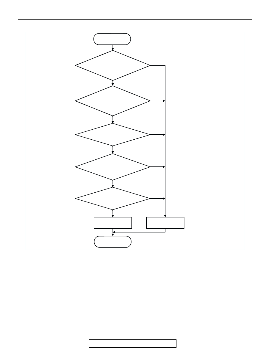
LOGIC FLOW CHARTS (Monitor Sequence)

.

DTC SET CONDITIONS

Check Conditions

• Transmission fluid temperature sensor voltage: 

4.5 volts or less.

• Transmission range switch: D, 3, 2 or L.

• Output speed: 900 r/min or more.

Judgement Criteria

• Vehicle speed: no signal change. (30 seconds)

.

OBD-II DRIVE CYCLE PATTERN
Start the engine, drive at 40 km/h (25 mph) or more 
continuously for one minute.

.

TROUBLESHOOTING HINTS (The most likely 
causes for this code to be set are:)

• Malfunction of the vehicle speed sensor circuit

• Damaged harness, connector

• Malfunction of the PCM

AC205180

START

N

OPG-B 

: Output speed

            (output shaft speed sensor)

Transmission range 
switch position is in 
D, 3, 2 or L range

Transmission fluid 
temperature sensor 
voltage < 4.5 V

N

OPG-B 

> 900 r/min

Is there no input from 
vehicle speed sensor

Continuous failure 
for 30 secs.

Yes

No

Good

Malfunction

END

Yes

No

Yes

No

Yes

No

Yes

No

AUTOMATIC TRANSMISSION DIAGNOSIS

TSB Revision

AUTOMATIC TRANSMISSION

23A-218

DIAGNOSIS

Required Special Tool:

• MB991958: Scan Tool (MUT-III Sub Assembly)

• MB991824: V.C.I.

• MB991827: MUT-III USB Cable

• MB991911: MUT-III Main Harness B

STEP 1. Check the speedometer.
Q: Is the speedometer operating properly?

YES : Go to Step 2.
NO :  Check the vehicle speed sensor. Refer to GROUP 54, 

Combination Meters Assembly and Vehicle Speed 
Sensor 

− Symptom Procedures − Speedometer does 

not work 

P.54-77

.

STEP 2. Using scan tool MB991958, check data list item 29: 
Vehicle Speed Sensor.

CAUTION

To prevent damage to scan tool MB991958, always turn the 
ignition switch to "LOCK" (OFF) position before connect-
ing or disconnecting scan tool MB991958.
(1) Connect scan tool MB991958 to the data link connector.
(2) Start the engine.
(3) Set scan tool MB991958 to data reading mode.

• Item 29: Vehicle Speed Sensor.

• Check that the speedometer and scan tool display 

speed match when driving at a vehicle speed of 40 
km/h (25 mph).

(4) Turn the ignition switch to the "LOCK" (OFF) position.
Q: Is the sensor operating properly?

YES : It can be assumed that this malfunction is intermittent. 

Refer to GROUP 00, How to Use 
Troubleshooting/Inspection Service Points 

− How to 

Cope with Intermittent Malfunction 

P.00-7

.

NO :  Go to Step 3.

AK303629AB

MB991911

MB991827

MB991824 

16-PIN

AUTOMATIC TRANSMISSION DIAGNOSIS

TSB Revision

AUTOMATIC TRANSMISSION

23A-219

STEP 3. Using an oscilloscope, check the vehicle speed 
sensor waveform at PCM connector C-91 by backprobing.

(1) Do not disconnect connector C-91.

(2) Connect an oscilloscope probe to PCM connector C-91 

terminal 80 by backprobing.

(3) Start the engine and drive the vehicle.

(4) Check the vehicle speed sensor waveform.

• The vehicle speed sensor waveform should show a pat-

tern similar to the illustration when running the vehicle.

(5) Turn the ignition switch to the "LOCK" (OFF) position.
Q: Is the waveform normal?

YES : Go to Step 6.
NO :  Go to Step 4.

AC202435

PCM

59
68

58
67

46 47

57

56

53
64

54

65

55

66

50

62

51

63

49

48
60 61

52

44

41 42 43

45

AC202435

PCM

CONNECTOR: C-91

AB

C-91 (GR)

71 72 73 74

75 76

77

78 79 80 81 82 83 84 85 86 87 88

90 91

92 93 94

95 96

97

98

89

AC001954

AJ

C-91 HARNESS CONNECTOR:
HARNESS SIDE 

OSCILLO-
SCOPE

PROBE

ACX02131

NORMAL WAVEFORM

(V)

AC

AUTOMATIC TRANSMISSION DIAGNOSIS

TSB Revision

AUTOMATIC TRANSMISSION

23A-220

STEP 4. Check PCM connector C-91 and intermediate 
connector C-16 for loose, corroded or damaged terminals, 
or terminals pushed back in the connector.

Q: Are the connectors and terminals in good condition?

YES : Go to Step 5.
NO :  Repair or replace the damaged components. Refer to 

GROUP 00E, Harness Connector Inspection 

P.00E-2

.

AC2023434

22

2021

10

9

8

1718

6 7

19

1415

4 5

1112

1 2 3

13

16

AB

CONNECTOR: C-16

C-16

AC202435

PCM

59
68

58
67

46 47

57

56

53
64

54

65

55

66

50

62

51

63

49

48
60 61

52

44

41 42 43

45

AC202435

PCM

CONNECTOR: C-91

AB

C-91 (GR)

71 72 73 74

75 76

77

78 79 80 81 82 83 84 85 86 87 88

90 91

92 93 94

95 96

97

98

89


Content   ..  661  662  663  664   ..