Mitsubishi Montero Sport (2004+). Manual - part 612


  Index      Mitsubishi     Mitsubishi Montero Sport - service repair manual 2004 year


Search            


Content   ..  610  611  612  613   ..


Mitsubishi Montero Sport (2004+). Manual - part 612


AUTOMATIC TRANSMISSION DIAGNOSIS

TSB Revision

AUTOMATIC TRANSMISSION

23A-13

A/T DIAGNOSTIC TROUBLESHOOTING STRATEGY

M1231108500127

Use these steps to plan your diagnostic strategy. If 
you follow them carefully, you will find most A/T mal-
functions.
1. Gather as much information as possible about the 

complaint from the customer.

2. Verify that the condition described by the 

customer exists.

3. Check the vehicle for any A/T Diagnostic Trouble 

Codes (DTCs).

4. If you can not verify the condition and there are no 

DTCs, the malfunction is intermittent. For 
information on how to cope with intermittent 
malfunctions, refer to GROUP 00, How to Use 
Troubleshooting/Inspection Service Points 

− How 

to Cope with Intermittent Malfunction 

P.00-7

.

5. If you can verify the condition but there are no 

DTCs, or the system can not communicate with 
the scan tool MB991958 (MUT-III sub assembly), 
refer to the Symptom Char

P.23A-41

.

6. If there is a DTC, record the number of the code, 

then erase the code from memory using scan tool 
MB991958 (MUT-III sub assembly).

7. Reconfirm the symptom with a Road Test.
8. If a DTC is set again, go to the Inspection Chart 

for Diagnostic Trouble Codes.

9. If a DTC is not set again, the malfunction is 

intermittent. For information on how to cope with 
intermittent malfunctions, refer to GROUP 00, 
How to Use Troubleshooting/Inspection Service 
Points 

− How to Cope with Intermittent 

Malfunction 

P.00-7

.

10.After repairs are completed, conduct a Road Test 

duplicating the complaint conditions to confirm the 
malfunction has been eliminated.

DIAGNOSTIC FUNCTION

M1231103300032

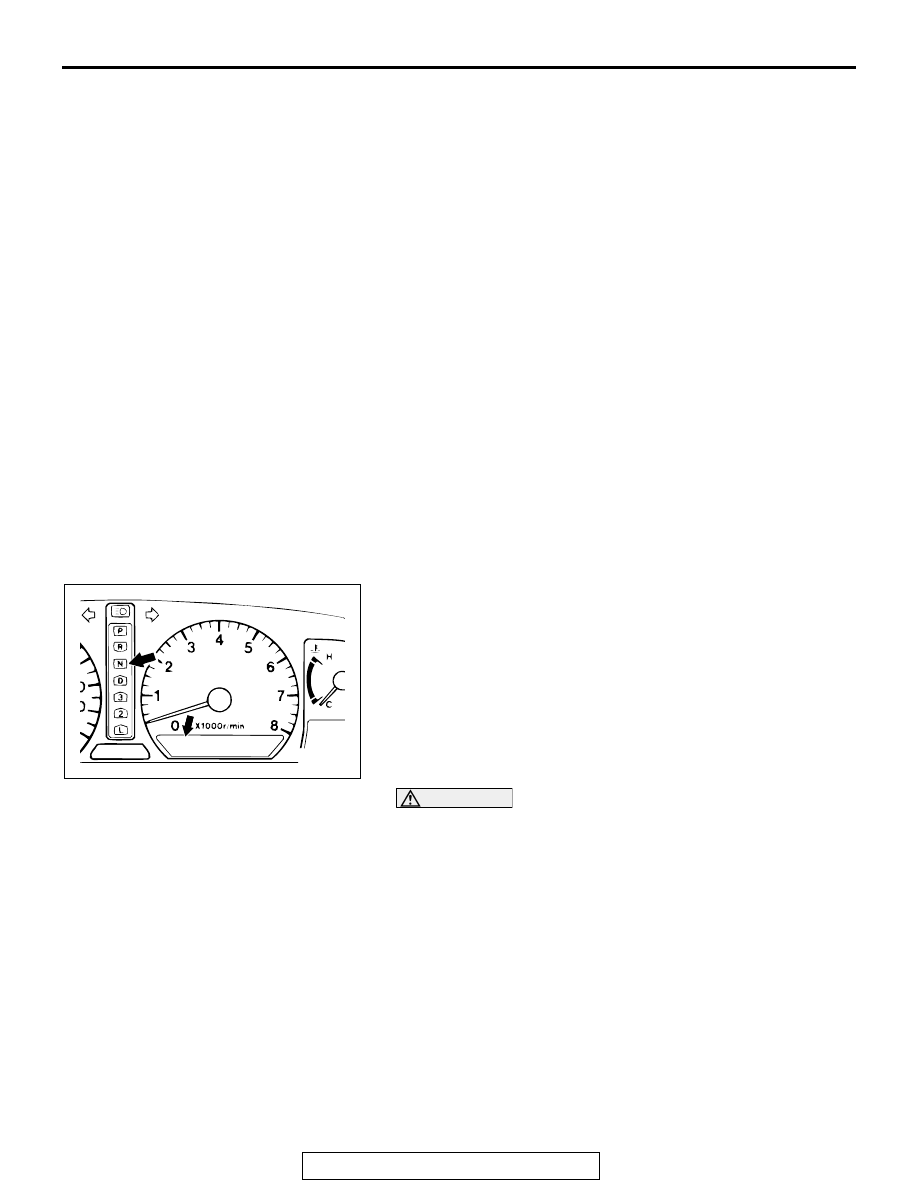
CHECK "N" RANGE LIGHT

The "N" range light flashes once per second if there is an 
abnormality in any of the items in the table below which are 
related to the A/T system. Check for diagnostic trouble codes if 
the "N" range light is flashing once per second. 

"N" range light flashing items

• Input shaft speed sensor

• Output shaft speed sensor

• Each solenoid valve

• Gear incorrect ratio

• A/T control relay system

CAUTION

If the "A/T TEMP" indicator light is illuminated, it means 
that the transmission fluid temperature is too high. Stop 
the vehicle in a safe place and wait until the "A/T TEMP" 
indicator light extinguishes. <4WD>

AC004016 AC

A/T

TEMP

AUTOMATIC TRANSMISSION DIAGNOSIS

TSB Revision

AUTOMATIC TRANSMISSION

23A-14

ON-BOARD DIAGNOSTICS

The powertrain control module (PCM) monitors its 
input/output signals (some signals all the time and 
others under specified conditions). When an irregular 
signal is initially monitored, the PCM decides that a 
malfunction has occurred and records the occur-
rence has diagnostic trouble code. There are 26 
diagnostic items. The diagnostic results can be read 
with a scan tool. Diagnostic trouble codes are kept in 
memory by direct battery feed. The codes are 
retained in memory even if the ignition switch is in 

the "LOCK" (OFF) position. Diagnostic trouble codes 
will, however, be erased when a battery terminal or 
the PCM connector is disconnected. In addition, the 
diagnostic trouble code can also be erased by the 
scan tool MB991958 (MUT-III sub assembly).
NOTE: If a sensor is disconnected when the ignition 
switch is in the "ON" position, a diagnostic trouble 
code is stored in memory. In this case, erase the 
DTC using scan tool MB991958 (MUT-III sub assem-
bly).
The 26 diagnostic items are displayed in numeric 
order.

HOW TO CONNECT THE SCAN TOOL (MUT-III)

Required Special Tools:

•  MB991958: Scan Tool (MUT-III Sub Assembly)

• MB991824: Vehicle Communication Interface (V.C.I.)

• MB991827: MUT-III USB Cable

• MB991911: MUT-III Main Harness B

CAUTION

To prevent damage to scan tool MB991958, always turn the 
ignition switch to the "LOCK" (OFF) position before con-
necting or disconnecting scan tool MB991958.
1. Ensure that the ignition switch is at the "LOCK" (OFF) 

position.

2. Start up the personal computer.
3. Connect special tool MB991827 to special tool MB991824 

and the personal computer.

4. Connect special tool MB991911 to special tool MB991824.
5. Connect special tool MB991911 to the data link connector.
6. Turn the power switch of special tool MB991824 to the "ON" 

position.
NOTE: When special tool MB991824 is energized, special 
tool MB991824 indicator light will be illuminated in a green 
color.

7. Start the MUT-III system on the personal computer.
NOTE: Disconnecting scan tool MB991958 is the reverse of the 
connecting sequence, making sure that the ignition switch is at 
the "LOCK" (OFF) position.

AK303629AB

MB991911

MB991827

MB991824 

16-PIN

AUTOMATIC TRANSMISSION DIAGNOSIS

TSB Revision

AUTOMATIC TRANSMISSION

23A-15

HOW TO READ AND ERASE DIAGNOSTIC 
TROUBLE CODES

Required Special Tools:

•  MB991958: Scan Tool (MUT-III Sub Assembly)

• MB991824: V.C.I.

• MB991827: MUT-III USB Cable

• MB991911: MUT-III Main Harness B

CAUTION

To prevent damage to scan tool MB991958, always turn the 
ignition switch to the "LOCK" (OFF) position before con-
necting or disconnecting scan tool MB991958.

NOTE: If the battery voltage is low, diagnostic trouble codes 
will not be set. Check the battery if scan tool MB991958 
does not display.

1. Connect scan tool MB991958 to the data link connector.
2. Turn the ignition switch to the "ON" position.
3. Select "Interactive Diagnosis" from the start-up screen.
4. Select "System select."
5. Choose "ELC-A/T" from the "POWER TRAIN" tab.
6. Select "MITSUBISHI."
7. Select "Diagnostic Trouble Code."
8. If a DTC is set, it is shown.
9. Choose "Erase DTCs" to erase the DTC.

AK303629AB

MB991911

MB991827

MB991824 

16-PIN

AUTOMATIC TRANSMISSION DIAGNOSIS

TSB Revision

AUTOMATIC TRANSMISSION

23A-16

HOW TO READ DATA LIST

Required Special Tools:

•  MB991958 : Scan Tool (MUT-III Sub Assembly)

• MB991824: V.C.I.

• MB991827: MUT-III USB Cable

• MB991911: MUT-III Main Harness B

CAUTION

To prevent damage to scan tool MB991958, always turn the 
ignition switch to the "LOCK" (OFF) position before con-
necting or disconnecting scan tool MB991958.
1. Connect scan tool MB991958 to the data link connector.
2. Turn the ignition switch to the "ON" position.
3. Select "Interactive Diagnosis" from the start-up screen.
4. Select "System select."
5. Choose "ELC-A/T" from the "POWER TRAIN" tab.
6. Select "MITSUBISHI."
7. Select "Data List."
8. Choose an appropriate item and select the "OK" button.

AK303629AB

MB991911

MB991827

MB991824 

16-PIN


Content   ..  610  611  612  613   ..