Mitsubishi Montero Sport (2004+). Manual - part 539


  Index      Mitsubishi     Mitsubishi Montero Sport - service repair manual 2004 year


Search            


Content   ..  537  538  539  540   ..


Mitsubishi Montero Sport (2004+). Manual - part 539


HEADLIGHT

TSB Revision

CHASSIS ELECTRICAL

54-143

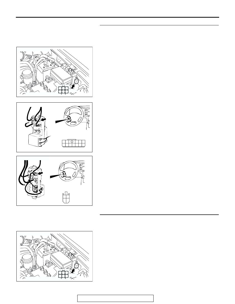
STEP 5. Check the connector between daytime running 
light-ECU connector A-96 and ignition switch for loose, 
corroded or damaged terminals, or terminals pushed back 
in the connector.

NOTE: After checking junction block connector D-01 and D-08, 
check the wires. If junction block connector D-01 and D-08 are 
damaged, repair or replace them. Refer to GROUP 00E, Har-
ness Connector Inspection 

P.00E-2

.

Q:  Are the connectors and terminals in good condition?

YES : Go to Step 6.
NO :  Repair or replace the damaged components. Refer to 

GROUP 00E, Harness Connector Inspection 

P.00E-2

.

STEP 6. Check the harness wire between daytime running 
light-ECU connector A-96 (terminal No.2) and ignition 

switch.

AC202180

1

2
5 4

3
6

COMPONENT SIDE

CONNECTOR: A-96

AC

A-96

AC200778

2

3

4

11 10 9 8 7

1
6

5

12

CONNECTOR: D-01

AB

D-01 COMPONENT SIDE

JUNCTION BLOCK (FRONT)

D-01

AC200773

M

3

1

4

2

CONNECTOR: D-08

D-08

COMPONENT SIDE

AB

AC202180

1

2
5 4

3
6

COMPONENT SIDE

CONNECTOR: A-96

AC

A-96

HEADLIGHT

TSB Revision

CHASSIS ELECTRICAL

54-144

NOTE: After checking junction block connector D-01 and D-08, 
check the wires. If junction block connector D-01 and D-08 are 
damaged, repair or replace them. Refer to GROUP 00E, Har-
ness Connector Inspection 

P.00E-2

.

Q: Are the harness wire between daytime running 

light-ECU connector A-96 (terminal No.2) and ignition 
switch in good condition?
YES : 
Go to Step 7.
NO :  Repair or replace the damaged components. Refer to 

GROUP 00E, Harness Connector Inspection 

P.00E-2

.

STEP 7. Check the daytime running light ground circuit at 
daytime running light connector A-96.

(1) Disconnect daytime running light connector A-96. 

(2) Measure the resistance between terminal 6 and ground.
Q: Is resistance between terminal 6 and ground less than 2 

ohms?
YES : 
Go to Step 9.
NO :  Go to Step 8.

AC200778

2

3

4

11 10 9 8 7

1
6

5

12

CONNECTOR: D-01

AB

D-01 COMPONENT SIDE

JUNCTION BLOCK (FRONT)

D-01

AC200773

M

3

1

4

2

CONNECTOR: D-08

D-08

COMPONENT SIDE

AB

AC202180

1

2
5 4

3
6

COMPONENT SIDE

CONNECTOR: A-96

AC

A-96

4

3 2 1

5

6

AC309263AB

A-96 HARNESS CONNECTOR:
COMPONENT SIDE

HEADLIGHT

TSB Revision

CHASSIS ELECTRICAL

54-145

STEP 8. Check the daytime running light-ECU lighting 
switch input circuit at daytime running light-ECU A-96.

(1) Disconnect the daytime running light-ECU.
(2) Turn the lighting switch "HEAD" position or passing switch 

"ON".

(3) Measure the voltage between terminal 5 and ground.
Q: Is battery positive voltage (approximately 12 volts) 

present?
YES : 
Go to Step 9.
NO :  Go to Step 10.

STEP 9. Check the connector between daytime running 
light-ECU connector A-96 and headlight relay connector 
A-52X for loose, corroded or damaged terminals, or 
terminals pushed back in the connector.

Q:  Is connector between daytime running light-ECU 

connector A-96 and headlight relay connector A-52X in 
good condition?
YES : 
Go to Step 10.
NO :  Repair or replace the damaged components. Refer to 

GROUP 00E, Harness Connector Inspection 

P.00E-2

.

AC202180

1

2
5 4

3
6

COMPONENT SIDE

CONNECTOR: A-96

AC

A-96

4

3 2 1

5

6

AC202561

A-96 HARNESS CONNECTOR:
COMPONENT SIDE

AB

AC202180

1

2
5 4

3
6

COMPONENT SIDE

CONNECTOR: A-96

AC

A-96

AC002583 AE

CONNECTOR: A-52X

2 3

5

4

1

A-52X

COMPONENT SIDE

HEADLIGHT

TSB Revision

CHASSIS ELECTRICAL

54-146

STEP 10. Check the harness wire between daytime running 
light-ECU connector A-96 (terminal No.5) and headlight 
relay connector A-52X

Q: Is harness wire between daytime running light-ECU 

connector A-96 (terminal No.5) and headlight relay 
connector A-52X in good condition?
YES : 
Go to Step 11.
NO :  Repair or replace the damaged components. Refer to 

GROUP 00E, Harness Connector Inspection 

P.00E-2

.

STEP 11. Check the daytime running light relay (lower) and 
(upper).

(1) Disconnect the daytime running light relay (lower) and 

(upper).

(2) Follow the table below to check for continuity of the daytime 

running light relay.

Q: Is the daytime running light relay continuity in good 

condition?
YES : 
Go to Step 12.
NO :  Replace the DRL relay (lower) or (upper).

AC202180

1

2
5 4

3
6

COMPONENT SIDE

CONNECTOR: A-96

AC

A-96

AC002583 AE

CONNECTOR: A-52X

2 3

5

4

1

A-52X

COMPONENT SIDE

BATTERY VOLTAGE TESTER 

CONNECTION

SPECIFIED 
CONDITION

Not applied

− 3

Open circuit

• Connect terminal 4 

to the positive 
battery terminal

• Connect terminal 2 

to the negative 
battery terminal

− 3

Less than 2 
ohms

AC202569

1

2

3

4

A-97 
DRL RELAY 
(LOWER)

A-98 
DRL RELAY 
(UPPER)

AB


Content   ..  537  538  539  540   ..