Mitsubishi Montero Sport (2004+). Manual - part 538


  Index      Mitsubishi     Mitsubishi Montero Sport - service repair manual 2004 year


Search            


Content   ..  536  537  538  539   ..


Mitsubishi Montero Sport (2004+). Manual - part 538


HEADLIGHT

TSB Revision

CHASSIS ELECTRICAL

54-139

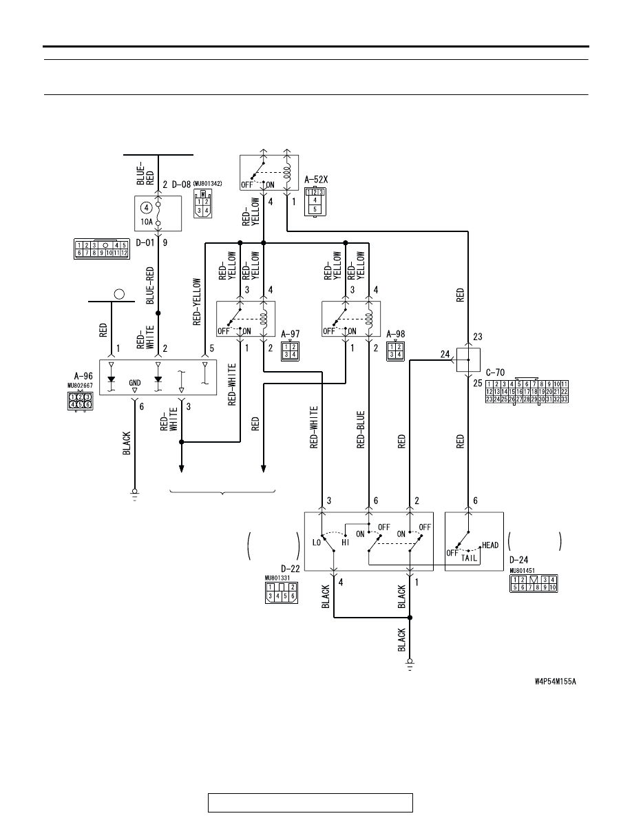
INSPECTION PROCEDURE 2: Daytime Running Light Function does not Illuminate .<Vehicles for 
CANADA>

FUSIBLE
LINK

JUNCTION
BLOCK

DRL-ECU

IGNITION
SWITCH (IG2)

COLUMN
SWITCH

DRL
LOWER
RELAY

DRL
UPPER
RELAY

HEADLIGHT
RELAY

(LO)

HEADLIGHT

(HI)

COLUMN
SWITCH

LIGHTING
SWITCH

11

JOINT 
CONNECTOR (3)

DIMMER·
PASSING
SWITCH

Day Time Running Light Circuit

HEADLIGHT

TSB Revision

CHASSIS ELECTRICAL

54-140

.

CIRCUIT OPERATION
If the ignition switch is turned to the "ON" position, 
and battery positive voltage will be applied from the 
daytime running light-ECU to the headlights.
Daytime running light-ECU terminal No.3 sends a 
constant voltage to the headlights at a constant fre-
quency. This causes the headlights to dim more than 
normal low-beam.
When the lighting switch is turned to the "HEAD" 
position or the passing switch is turned on, daytime 
running light-ECU terminal No.3 ceases the voltage 
supply. This causes the headlights to illuminate at 
normal low-beam.

.

TECHNICAL DESCRIPTION (COMMENT)
The cause may be a faulty daytime running light cir-
cuit or a faulty daytime running light-ECU. 

.

 TROUBLESHOOTING HINTS

• Malfunction of the daytime running light-ECU

• Malfunction of the daytime running light relay

• Damaged harness wires or connectors

.

AC002583AD

CONNECTOR: A-52X

A-52X

AC202180

CONNECTORS: A-96, A-97, A-98

AB

A-96

A-97

A-98

AC003830

CONNECTOR: C-70

AJ

 C-70

AC003522

CONNECTOR: D-01

AC

JUNCTION BLOCK (FRONT)

D-01

AC003519

CONNECTOR: D-08

AE

JUNCTION BLOCK (REAR)

D-08

AC202556

CONNECTORS: D-22, D-24

AC

D-22

D-24

HEADLIGHT

TSB Revision

CHASSIS ELECTRICAL

54-141

DIAGNOSIS

Required Special Tool:

• MB991223: Harness Set

STEP 1. Check the daytime running light-ECU power 
supply (battery) circuit at daytime running light-ECU 
connector A-96. 

(1) Disconnect daytime running light-ECU connector A-96.

(2) Measure the voltage between terminal 1 and ground. 
Q: Is the voltage 12 volts (battery positive voltage) between 

terminal 1 and ground?
YES : 
Go to Step 3.
NO :  Go to Step 2.

STEP 2. Check daytime running light-ECU connector A-96 
for loose, corroded or damaged terminals, or terminals 
pushed back in the connector.

Q: Are the connectors and terminals in good condition?

YES : Go to Step 3.
NO :  Repair or replace the damaged components. Refer to 

GROUP 00E, Harness Connector Inspection 

P.00E-2

.

AC202180

1

2
5 4

3
6

COMPONENT SIDE

CONNECTOR: A-96

AC

A-96

4

3 2 1

5

6

AC002360

A-96 HARNESS CONNECTOR:
COMPONENT SIDE

AC

AC202180

1

2
5 4

3
6

COMPONENT SIDE

CONNECTOR: A-96

AC

A-96

HEADLIGHT

TSB Revision

CHASSIS ELECTRICAL

54-142

STEP 3. Check the harness wires between daytime running 
light-ECU connector A-96 (terminal No.1) and fusible link 
No. 11.

Q: Are the harness wires between daytime running 

light-ECU connector A-96 (terminal No.1) and fusible 
link No. 11 in good condition?
YES : 
Go to step 4.
NO :  Repair or replace the damaged components. Refer to 

GROUP 00E, Harness Connector Inspection 

P.00E-2

.

STEP 4. Check the daytime running light-ECU power 
supply circuit (IG2) at the daytime running light-ECU 
connector A-96.

(1) Disconnect the daytime running light-ECU connector A-96.
(2) Turn the ignition switch "ON" position.

(3) Measure the resistance between terminal 2 and ground.
Q: Is battery positive voltage (approximately 12 volts) 

present?
YES : 
Go to Step 7.
NO :  Go to Step 5.

AC202180

1

2
5 4

3
6

COMPONENT SIDE

CONNECTOR: A-96

AC

A-96

AC202180

1

2
5 4

3
6

COMPONENT SIDE

CONNECTOR: A-96

AC

A-96

4

3 2 1

5

6

AC309262 AB

A-96 HARNESS CONNECTOR:
COMPONENT SIDE


Content   ..  536  537  538  539   ..