Mitsubishi Montero Sport (2004+). Manual - part 536


  Index      Mitsubishi     Mitsubishi Montero Sport - service repair manual 2004 year


Search            


Content   ..  534  535  536  537   ..


Mitsubishi Montero Sport (2004+). Manual - part 536


HEADLIGHT

TSB Revision

CHASSIS ELECTRICAL

54-131

NOTE: After inspecting junction block connector D-14 and 
intermediate connector E-42, inspect the wire. If junction block 
connector D-14 and intermediate connector E-42 are dam-
aged, repair or replace them. Refer to GROUP 00E, Harness 
Connector Inspection 

P.00E-2

.

Q: Are the harness wires between driver's side door switch 

connector E-33 (terminal No.2) and ETACS-ECU 
connector D-11 (terminal No.9) in good condition?
YES : 
Go to Step 8.
NO :  Repair the harness wires. Then check that the 

malfunction is eliminated.

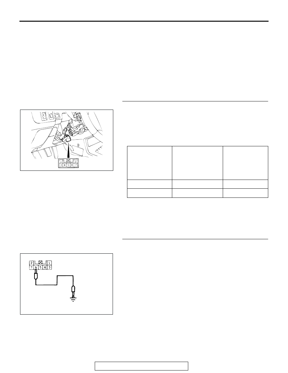
STEP 8. Check for continuity of the key reminder switch.

(1) Remove the driver's side under cover.
(2) Remove the column covers, lower and upper.

(3) Disconnect wiring connector D-16 from the key reminder 

switch and measure at the key reminder switch side.

(4) Follow the table below to measure the resistance between 

terminal numbers 4 and 6.

Q: Does the measured resistance value correspond with 

this range?
YES : 
Go to Step 9.
NO :  Replace the key reminder switch. Then check that the 

malfunction is eliminated.

STEP 9. Check the input signal from the key reminder 
switch.

Check that the tone alarm stops sounding when terminal num-
ber 6 is grounded.
Q: Does the tone alarm stop sounding?

YES : Go to Step 10.
NO :  Go to Step 12.

IGNITION KEY 
POSITION

IGNITION KEY 
REMINDER 
SWITCH 
CONNECTOR D-16 
TERMINAL NO.

SPECIFIED 
CONDITION

Pulled out

− 6 

Less than 2 ohms

Inserted

− 6

Open circuit

AC002730

AC002731AE

D-16 
HARNESS CONNECTOR:
COMPONENT SIDE

HEADLIGHT

TSB Revision

CHASSIS ELECTRICAL

54-132

STEP 10. Check key reminder switch connector D-16 for 
damage for loose, corroded or damaged terminals, or 
terminals pushed back in the connector.

Q: Is key reminder switch connector D-16 in good 

condition?
YES : 
Go to step 11.
NO :  Repair or replace it. Refer to GROUP 00E, Harness 

Connector Inspection 

P.00E-2

STEP 11. Check the harness wire between key reminder 
switch connector D-16 (terminal No.4) and body ground.

Q: Is the resistance wire between key reminder switch D-16 

(terminal No.4) and body ground in good condition?
YES : 
There is no action to be taken.
NO :  Repair or replace it. Refer to GROUP 00E, Harness 

Connector Inspection 

P.00E-2

AC202060

4

5

3

1

6

7

2

AC202060

4

5

3

1

6

7

2

HEADLIGHT

TSB Revision

CHASSIS ELECTRICAL

54-133

STEP 12. Check the harness wire between key reminder 
switch connector D-16 (terminal No.6) and ETACS-ECU 
connector D-11 (terminal No.8).

1

2

4

5

3

6

8

9

7

10

11

13

14

12

16

17

201918

15

AC201086

AC202060

4

5

3

1

6

7

2

8

19

7

6

5

16

15

17 18

4

3

2

10 11 12 13

1
9

14

AC201910

CONNECTOR: C-72

AB

C-72 (B)

HEADLIGHT

TSB Revision

CHASSIS ELECTRICAL

54-134

NOTE: After checking intermediate connector C-72 and D-13, 
check the wires. If intermediate connector C-72 and D-13 are 
damaged, repair or replace them. Refer to GROUP 00E, Har-
ness Connector Inspection 

P.00E-2

.

Q: Is the harness wire between key reminder switch D-16 

(terminal No.6) and ETACS-ECU connector D-11 
(terminal No.8) in good condition?
YES : 
Go to Step 13.
NO :  Repair or replace it. Refer to GROUP 00E, Harness 

Connector Inspection 

P.00E-2

.

STEP 13. Measure the voltage at the input signal from the 
ignition switch.

(1) Remove the ETACS-ECU and measure at the junction 

block side (connector D-11).

(2) Turn the ignition switch "ON".
(3) Measure the voltage between terminal number 3 and body 

ground.

• The measured value should be approximately 12 volts 

(battery positive voltage).

Q: Does the measured voltage correspond with this range?

YES : Check that the malfunction is eliminated.
NO :  Go to Step 14.

STEP 14. Check ETACS-ECU connector D-11 for damage 
for loose, corroded or damaged terminals, or terminals 
pushed back in the connector.

Q: Is ETACS-ECU connector D-11 in good condition?

YES : Go to step 15.
NO :  Repair or replace it. Refer to GROUP 00E, Harness 

Connector Inspection 

P.00E-2

AC201084

JUNCTION 
BLOCK (REAR)

D-11

COMPONENT SIDE

AB

CONNECTOR: D-11

1

2

3

4

5

7

9

10

6

8

11

12

AC004032   

AC

D-11 
HARNESS CONNECTOR:
COMPONENT SIDE

AC201084

JUNCTION 
BLOCK (REAR)

D-11

COMPONENT SIDE

AB

CONNECTOR: D-11


Content   ..  534  535  536  537   ..