Mitsubishi Montero Sport (2004+). Manual - part 483


  Index      Mitsubishi     Mitsubishi Montero Sport - service repair manual 2004 year


Search            


Content   ..  481  482  483  484   ..


Mitsubishi Montero Sport (2004+). Manual - part 483


SUNROOF ASSEMBLY

TSB Revision

BODY

42-187

NOTE: After inspecting junction block connector D-14 and 
intermediate connector E-42 inspect the wire. If junction block 
connector D-14 or intermediate connector E-42 is damaged, 
repair or replace it. Refer to GROUP 00E 

P.00E-2

, Harness 

Connector Inspection. Then go to Step 11.
Q: Are there any damaged harness wires between 

ETACS-ECU connector D-11 (terminal No.9), D-26 
(terminal No.23) and driver's door switch connectors 
E-33 (terminal No.2), front passenger’s side door switch 
connector E-46 (terminal No.2)?
YES : 
Repair or replace the harness wire, then go to Step11.
NO :  Replace the ETACS-ECU and then go to Step11.

STEP 9. Check ETACS-ECU connector D-11 for loose, 
corroded or damaged terminals, or terminals pushed back 
in the connector.
Q: Is ETACS-ECU connector D-11 good condition?

YES : Go to Step 10. 
NO :  Repair or replace the damaged components. Refer to 

GROUP 00E 

P.00E-2

, Harness Connector inspection.

STEP 10. Check the harness wire between ETACS-ECU 
connector D-11 (terminal No.3) and ignition switch.
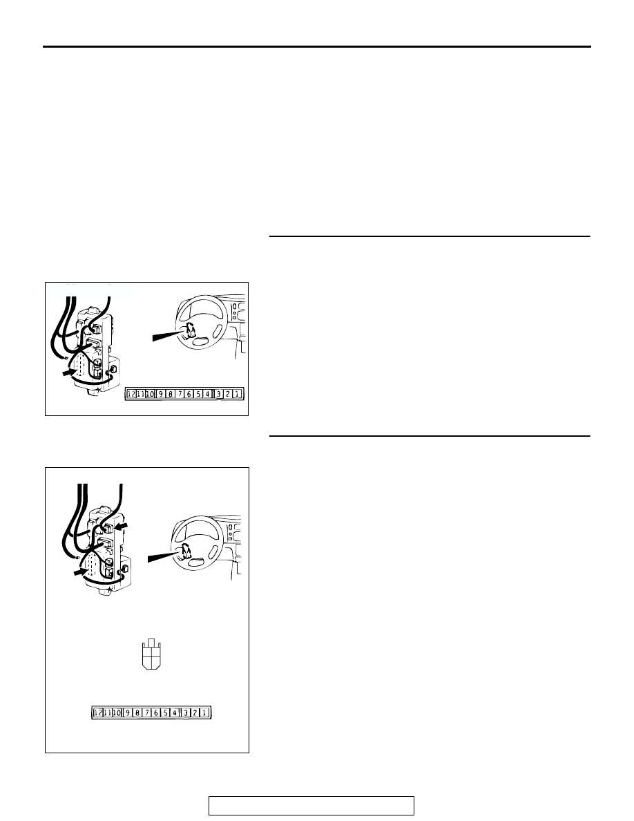
AC201084

JUNCTION 
BLOCK (REAR)

D-11

COMPONENT SIDE

AB

CONNECTOR: D-11

AC201941

M

3

1

4

2

CONNECTORS: D-08, D-11

AC

D-11

D-08

D-08 COMPONENT SIDE

D-11 COMPONENT SIDE

SUNROOF ASSEMBLY

TSB Revision

BODY

42-188

NOTE: After inspecting junction block connector D-08 inspect 
the wire. If junction block connector D-08 is damaged, repair or 
replace it. Refer to GROUP 00E 

P.00E-2

, Harness Connector 

Inspection. Then go to Step 11.
Q: Are ETACS-ECU connector D-11 and ignition switch in 

good condition?
YES : 
Go to step 11.
NO :  Repair or replace the harness wire. Refer to GROUP 

00E 

P.00E-2

, Harness Connector inspection.

STEP 11. Retest the system.
Q: Does the sunroof timer function operate normally?

YES : The procedure is complete.
NO :  Return to Step 1.

SUNROOF ASSEMBLY

TSB Revision

BODY

42-189

INSPECTION PROCEDURE 5: Safety Mechanism does not Function.

SUNROOF-
ECU

JUNCTION 
BLOCK

JUNCTION 
BLOCK

FUSIBLE
LINK

8

Sunroof-ECU Power Supply for Safety Mechanism and Ground Circuit

AC309309AB

C-01

CONNECTOR: C-01

AC004314 AH

CONNECTOR: D-02

JUNCTION

BLOCK (FRONT)

D-02

SUNROOF ASSEMBLY

TSB Revision

BODY

42-190

.

CIRCUIT OPERATION
The power for the safety mechanism circuit in the 
sunroof-ECU is supplied from fusible link number 8.

.

TECHNICAL DESCRIPTION (COMMENT)
The cause may be a malfunction of the sunroof-ECU 
power supply for safety mechanism circuit system or 
of the ground circuit system.

.

TROUBLESHOOTING HINTS

• Malfunction of the sunroof-ECU

• Damaged harness wires or connectors

DIAGNOSIS

STEP 1. Check sunroof-ECU connector E-07 for loose, 
corroded or damaged terminals, or terminals pushed back 
in the connector.
Q: Is sunroof-ECU connector E-07 damaged?

YES : Repair or replace the damaged components. Refer to 

GROUP 00E 

P.00E-2

, Harness Connector 

Inspection. Then go to Step 5.

NO :  Go to Step 2.

AC004311BH

CONNECTOR: D-09

JUNCTION

BLOCK (REAR)

D-09

AC004958AG

CONNECTOR: E-07

E-07

AC004958AH

CONNECTOR: E-07

E-07

COMPONENT SIDE


Content   ..  481  482  483  484   ..