Mitsubishi Montero Sport (2004+). Manual - part 481


  Index      Mitsubishi     Mitsubishi Montero Sport - service repair manual 2004 year


Search            


Content   ..  479  480  481  482   ..


Mitsubishi Montero Sport (2004+). Manual - part 481


SUNROOF ASSEMBLY

TSB Revision

BODY

42-179

DIAGNOSIS

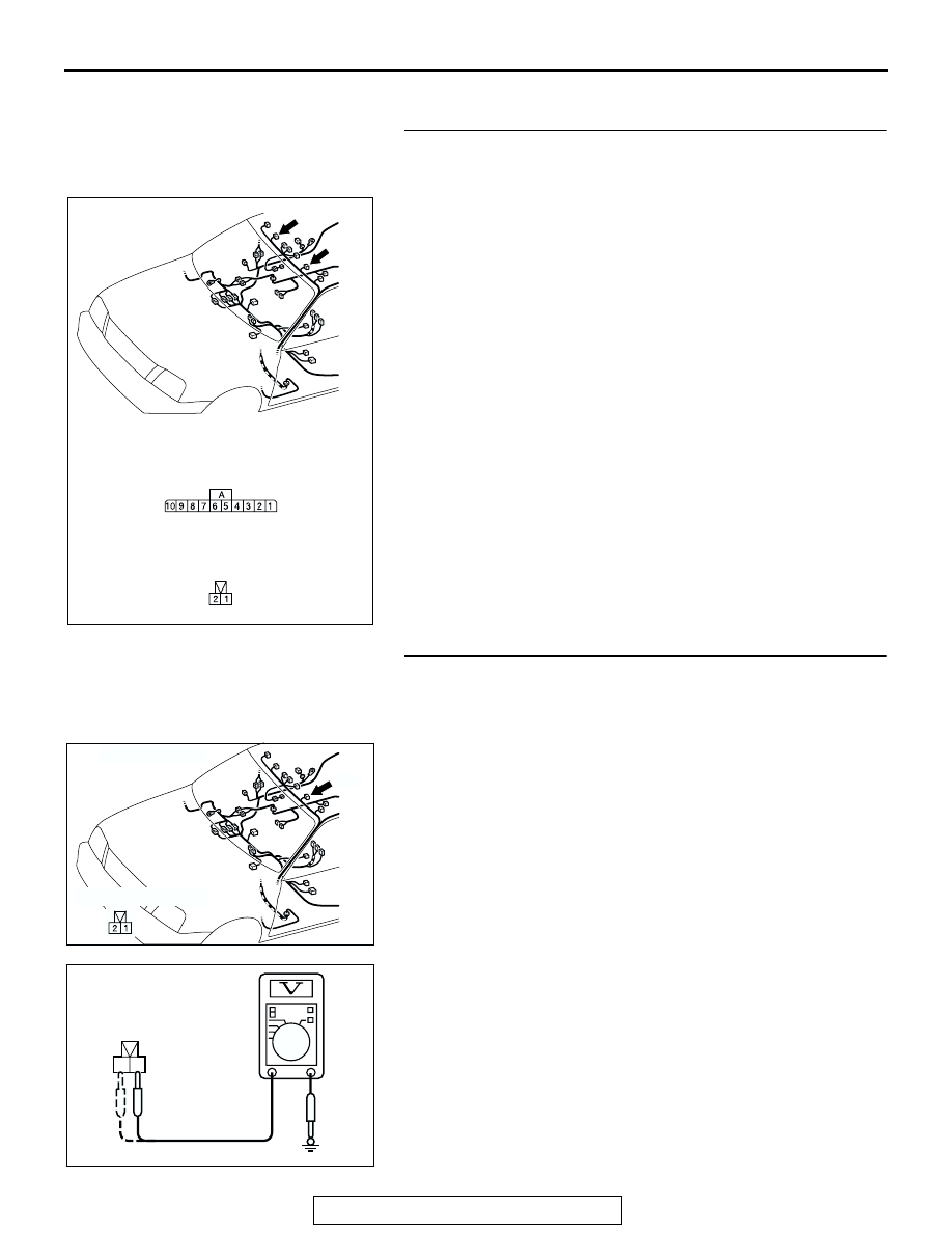
STEP 1. Check sunroof-ECU connector E-07 and sunroof 
motor connector E-09 for loose, corroded or damaged 
terminals, or terminals pushed back in the connector.
Q: Are sunroof connector E-07 and sunroof switch 

connector E-09 damaged?
YES : 
Repair or replace the damaged components. Refer to 

GROUP 00E 

P.00E-2

, Harness Connector 

Inspection. Then go to Step 5.

NO :  Go to Step 2.

STEP 2. Measure the power supply/ground line at sunroof 
motor connector E-09.
(1) Remove the headlining. (Refer to GROUP 52A, Headlining 

P.52A-42

.)

(2) Disconnect sunroof motor connector E-09 and measure at 

the harness side.

(3) Turn the ignition key "ON".

(4) Measure the voltage between terminal 1 and ground while 

the sunroof switch is depressing to the slide open/close 
position. And measure the voltage between terminal 2 and 
ground while the sunroof switch is depressing to the slide 
open/close position.

• The measured value should be approximately 12 volts 

(battery positive voltage).

Q: Does the measured voltage correspond with this range?

YES : Go to Step 4.
NO :  Go to Step 3.

AC309311

CONNECTORS: E-07, E-09

E-07

E-09

E-07 COMPONENT SIDE

E-09 COMPONENT SIDE

AC

AC004958AJ

CONNECTOR: E-09

E-09

COMPONENT SIDE

2 1

AC004960 AC

E-09 
HARNESS CONNECTOR:
COMPONENT SIDE

SUNROOF ASSEMBLY

TSB Revision

BODY

42-180

STEP 3. Check the harness wires between sunroof-ECU 
connector E-07 (terminal No.9 and 10) and sunroof motor 
connector E-09 (terminal No.1 and 2).
Q: Are there any damaged wires between sunroof-ECU 

connector E-07 (terminal No.9 and 10) and sunroof 
motor connector E-09 (terminal No.1 and 2)?
YES : 
Repair or replace the harness wire, then go to Step 5.
NO :  Replace the sunroof-ECU. Then go to Step 4.

STEP 4. Check the sunroof motor.
(1) Remove the sunroof motor. (Refer to 

P.42-200

.)

(2) Follow the table below to check for the direction of rotation 

of the drive gear when the battery is connected to the 
connector.

Q: Is the sunroof motor damaged?

YES : Replace sunroof motor, then go to Step 5.
NO :  Go to Step 5.

STEP 5. Retest the system.
Q: Does the sunroof open and close normally?

YES : The procedure is complete.
NO :  Return to Step 1.

AC309311

CONNECTORS: E-07, E-09

E-07

E-09

E-07 COMPONENT SIDE

E-09 COMPONENT SIDE

AC

BATTERY CONNECTION

DRIVE GEAR ROTATION 
DIRECTION

Connect terminal 1 to the 
positive battery terminal
Connect terminal 2 to the 
negative battery terminal

The drive gear rotates 
counterclockwise

Connect terminal 2 to the 
positive battery terminal
Connect terminal 1 to the 
negative battery terminal

The drive gear rotates 
clockwise

2

1

AC003809

LEFT 
ROTATION

DRIVE GEAR

RIGHT
ROTATION

AB

SUNROOF ASSEMBLY

TSB Revision

BODY

42-181

INSPECTION PROCEDURE 4: Sunroof Timer Function does not Work Normally <Vehicles with 
keyless entry system>.

Front Door Switch Circuit

SUNROOF ASSEMBLY

TSB Revision

BODY

42-182

.

TECHNICAL DESCRIPTION (COMMENT)
The ETACS-ECU operates the sunroof timer func-
tion, based on input signals from the following 
switches:

• Ignition switch (IG1)

• Driver's or front passenger's door switch

If the sunroof timer function do not work normally, the 
input signal circuit or the ETACS-ECU may be defec-
tive.

.

TROUBLESHOOTING HINTS

• Malfunction of the front door switch

• Malfunction of the ignition switch

• Malfunction of the ETACS-ECU

• Damaged harness wires or connectors

DIAGNOSIS

Required Special Tools:

• MB991223: Harness Set

• MB991529: Diagnostic Trouble Code Check Harness

• MB991958: Scan Tool (MUT-III Sub Assembly)

• MB991824: Vehicle Communication Interface (V.C.I.)

• MB991827: MUT-III USB Cable

• MB991911: MUT-III Main Harness B

STEP 1. Choose method of the ETACS-ECU input signal 
check.
Q: Is the ETACS-ECU input signal check performed by 

scan tool MB991958 or a voltmeter?
By scan tool MB991958 : 
Go to Step 2.
By a voltmeter : Go to Step 3.

AC004311

JUNCTION BLOCK(REAR)

CONNECTORS: D-08, D-11, D-14, D-26

BF

D-14 (B)

D-11

D-26 (B)

D-08

AC004329AH

E-42

E-46

E-33

CONNECTORS: E-33, E-42, E-46


Content   ..  479  480  481  482   ..