Mitsubishi Montero Sport (2004+). Manual - part 479


  Index      Mitsubishi     Mitsubishi Montero Sport - service repair manual 2004 year


Search            


Content   ..  477  478  479  480   ..


Mitsubishi Montero Sport (2004+). Manual - part 479


SUNROOF ASSEMBLY

TSB Revision

BODY

42-171

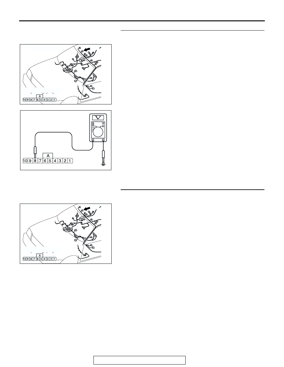
STEP 2. Measure the power supply line voltage at 
sunroof-ECU connector E-07.
(1) Remove the headlining. (Refer to GROUP 52A, Headlining 

P.52A-42

.)

(2) Disconnect sunroof-ECU connector E-07 and measure at 

the harness side.

(3) Turn the ignition key "ON".
(4) Measure the voltage between terminal 8 and ground.

• The measured value should be approximately 12 volts 

(battery positive voltage).

Q: Is battery positive voltage (approximately 12 volts) 

present?
YES : 
Go to Step 5.
NO <Vehicles without keyless entry system> : Go to 

Step 3.

NO <vehicles with keyless entry system> : Go to Step 4.

STEP 3. Check the harness wires between ignition switch 
(IG1) and sunroof-ECU connector E-07 (terminal No.8).

AC004958AH

CONNECTOR: E-07

E-07

COMPONENT SIDE

AC309310AB

E-07 HARNESS CONNECTOR:
COMPONENT SIDE

AC004958AH

CONNECTOR: E-07

E-07

COMPONENT SIDE

SUNROOF ASSEMBLY

TSB Revision

BODY

42-172

NOTE: After inspecting intermediate connector C-01, junction 
block D-08 and D-14 inspect the wire. If intermediate connector 
C-01, junction block D-08 or D-14 is damaged, repair or replace 
it. Refer to GROUP 00E 

P.00E-2

, Harness Connector Inspec-

tion. Then go to Step 4.
Q: Is the harness wire damaged?

YES : Repair or replace the harness wire, then go to Step 4.
NO :  Go to Step 5.

AC309309AC

C-01

CONNECTOR: C-01

AC201994

M

3

1

4

2

1

2

3

4

5

7 6

16151413121110 9 8

CONNECTORS: D-08, D-14

JUNCTION BLOCK (REAR)

D-08

D-14 (B)

D-14 COMPONENT SIDE

D-08 COMPONENT SIDE

AB

SUNROOF ASSEMBLY

TSB Revision

BODY

42-173

STEP 4. Check the harness wires between power window 
relay connector C-75X (terminal No.1) and sunroof-ECU 
connector E-07 (terminal No.8).
Q: Is the harness wire damaged?

YES : Repair or replace the harness wire, then go to Step 5.
NO :  Go to Step 6.

STEP 5. Check the harness wire between sunroof-ECU 
connector E-07 (terminals No.2 and No.6) and ground.

NOTE: After inspecting intermediate connector C-01, inspect 
the wire. If intermediate connector C-01 are damaged, repair or 
replace them. Refer to GROUP 00E 

P.00E-2

, Harness Con-

nector Inspection. Then go to Step 6.
Q: Is the harness wire between sunroof-ECU connector 

E-07 (terminal No.2) and ground damaged?
YES : 
Repair or replace the harness wire, then go to Step 6.
NO :  Replace the sunroof-ECU. Then go to Step 6.

AC202074

4

2 1

3

CONNECTOR: C-75X

AB

C-75X

COMPONENT 

SIDE

AC004958AH

CONNECTOR: E-07

E-07

COMPONENT SIDE

AC004958AH

CONNECTOR: E-07

E-07

COMPONENT SIDE

AC309309AC

C-01

CONNECTOR: C-01

SUNROOF ASSEMBLY

TSB Revision

BODY

42-174

STEP 6. Retest the system
Q: Does the sunroof open and close normally?

YES : The procedure is complete.
NO :  Return to Step 1.

INSPECTION PROCEDURE 2: The Sunroof does not Operate when the Sunroof Switch is Operated.

.

CIRCUIT OPERATION
The sunroof-ECU monitors the sunroof switch status 
(slide open, slide closed, tilt down, tilt up) and oper-
ates the sunroof motor.

.

TECHNICAL DESCRIPTION (COMMENT)
The cause may be a malfunction of the sunroof 
switch power supply circuit system or of the ground 
circuit system.

.

TROUBLESHOOTING HINTS

• Malfunction of the sunroof-ECU

• Malfunction of the sunroof switch

• Damaged harness wires or connectors

SUNROOF
SWITCH

SUNROOF-
ECU

DETECTION
CIRCUIT

Sunroof Switch Circuit

AC309309AB

C-01

CONNECTOR: C-01

AC004958AC

CONNECTORS: E-03, E-07

E-07

E-03


Content   ..  477  478  479  480   ..