Mitsubishi Montero Sport (2004+). Manual - part 478


  Index      Mitsubishi     Mitsubishi Montero Sport - service repair manual 2004 year


Search            


Content   ..  476  477  478  479   ..


Mitsubishi Montero Sport (2004+). Manual - part 478


KEYLESS ENTRY SYSTEM

TSB Revision

BODY

42-167

3. Adjustment of functions

KEYLESS ENTRY SYSTEM

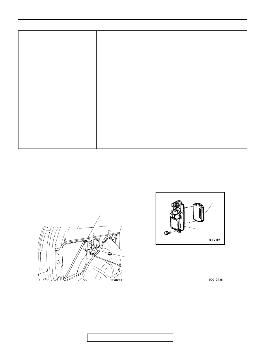
REMOVAL AND INSTALLATION

M1428001300107

FUNCTION

ADJUSTMENT PROCEDURE

Keyless entry answerback function When the transmitter lock switch is turned on twice continuously within 

2 seconds, the lock answerback function toggles on and off.

• If the function toggles on, the tone alarm sounds once (default 

condition).

• If the function toggles off, the tone alarm sounds twice.

When the transmitter unlock switch is turned on twice continuously 
within 2 seconds, the unlock answerback function toggles on and off.

• If the function toggles on, the tone alarm sounds once (default 

condition).

• If the function toggles off, the tone alarm sounds twice.

Initialization of all the ETACS-ECU 
functions (From deactivation to 
activation)

When the taillight switch remains on for more than 20 seconds, the 
tone alarm sounds twice and then the keyless entry system 
answerback.
The tone alarm will sound in 10 seconds (indicating that the 
ETACS-ECU enters the adjustment mode), but the washer switch 
must remains off for 20 seconds in order to initialize all the functions.
If the taillight switch remains on for more than 20 seconds without 
entering the adjustment mode, the system enters the adjustment 
mode in 10 seconds, but does not initialize all of the functions.

AC005037AB

JUNCTION
BLOCK

1

2

5 N·m
44in-lb

KEYLESS ENTRY RECEIVER-ECU 
REMOVAL STEPS
• QUARTER TRIM, LOWER (REFER 

TO GROUP 52A, TRIM 

P.52A-41

.)

1. KEYLESS ENTRY RECEIVER-ECU

ETACS-ECU REMOVAL
2. ETACS-ECU

SUNROOF ASSEMBLY

TSB Revision

BODY

42-168

INSPECTION

M1428001400030

HAZARD WARNING RELAY CONTINUITY CHECK

SUNROOF ASSEMBLY

GENERAL INFORMATION

M1426000100148

A motor-driven outer slide-type glass sunroof with a 
tilt-up mechanism is provided as an option. Even 
when the sunroof is fully closed, a sufficient amount 
of lighting and a feeling of openness can still be 
obtained by opening the sunroof sunshade.

SUNROOF DIAGNOSIS

INTRODUCTION TO SUNROOF DIAGNOSIS

M1426003100051

The operation of the sunroof is controlled by the sun-
roof-ECU. By operating the sunroof switch, the sun-
roof-ECU rotates the sunroof motor. If the following 
type of symptom occurs, there may be a fault

• The sunroof motor does not conduct load detec-

tion operation.

• The illumination light of the sunroof switch does 

not illuminate.

• The sunroof does not operate.

SUNROOF DIAGNOSTIC TROUBLESHOOTING STRATEGY

M1426001700046

Use these steps to plan your diagnostic strategy. If 
you follow them carefully, you will be sure that you 
have exhausted most of the possible ways to find a 
sunroof fault.
1. Gather information from customer.

2. Verify that the condition described by the 

customer exists.

3. Find the malfunction by following the Symptom 

Chart.

4. Verify that the malfunction is eliminated.

BATTERY 
VOLTAGE

TESTER 
CONNECTION

SPECIFIED 
CONDITION

Not applied

− 8 

− 5 

Open circuit

• Connect 

terminal 6 to the 
positive battery 
terminal

• Connect 

terminal 1 to the 
negative battery 
terminal

− 8 

− 5 

Less than 2 ohms

AC005060

AC004698

1

2 3

4 5 6 7 8

1

8

4

5

6

2

AC002588

AB

HAZARD WARING
RELAY

SUNROOF ASSEMBLY

TSB Revision

BODY

42-169

SYMPTOM CHART

M1426002000125

SYMPTOM PROCEDURES

INSPECTION PROCEDURE 1: The Sunroof does not Operate when the Ignition Switch is Turned to 
"ON".

SYMPTOM

INSPECTION 
PROCEDURE

REFERENCE PAGE

The sunroof does not operate when the ignition switch is 
turned to "ON".

1

P.42-169

The sunroof does not operate when the sunroof switch is 
operated.

2

P.42-174

The sunroof motor does not operate.

3

P.42-178

Sunroof timer function does not work normally <Vehicles 
with keyless entry system>.

4

P.42-181

Safety mechanism does not function.

5

P.42-189

IGNITION
SWITCH (IG1)

POWER WINDOW
RELAY

SUNROOF-
ECU

IGNITION SWITCH
INPUT CIRCUIT

JUNCTION 
BLOCK

NOTE

VEHICLES WITHOUT
KEYLESS ENTRY SYSTEM
VEHICLES WITH
KEYLESS ENTRY SYSTEM

Sunroof-ECU Power Supply and Ground Circuit

SUNROOF ASSEMBLY

TSB Revision

BODY

42-170

.

CIRCUIT OPERATION
The sunroof-ECU power is supplied from ignition 
switch (IG1).

.

TECHNICAL DESCRIPTION (COMMENT)
The cause may be a malfunction of the sunroof-ECU 
power supply circuit system or the ground circuit sys-
tem.

.

TROUBLESHOOTING HINTS

• Malfunction of the sunroof-ECU

• Damaged harness wires or connectors

DIAGNOSIS

STEP 1. Check sunroof-ECU connector E-07 for loose, 
corroded or damaged terminals, or terminals pushed back 
in the connector
Q: Is sunroof-ECU connector E-07 damaged?

YES : Repair or replace the damaged components. Refer to 

GROUP 00E 

P.00E-2

, Harness Connector 

Inspection. Then go to Step 6.

NO :  Go to Step 2.

AC309309AB

C-01

CONNECTOR: C-01

AC003622

CONNECTOR: C-75X

AE

C-75X

AC004311AI

CONNECTORS: D-08, D-14

JUNCTION

BLOCK (REAR)

D-08

D-14

AC004958AG

CONNECTOR: E-07

E-07

AC004958AH

CONNECTOR: E-07

E-07

COMPONENT SIDE


Content   ..  476  477  478  479   ..