Mitsubishi Montero Sport (2004+). Manual - part 482


  Index      Mitsubishi     Mitsubishi Montero Sport - service repair manual 2004 year


Search            


Content   ..  480  481  482  483   ..


Mitsubishi Montero Sport (2004+). Manual - part 482


SUNROOF ASSEMBLY

TSB Revision

BODY

42-183

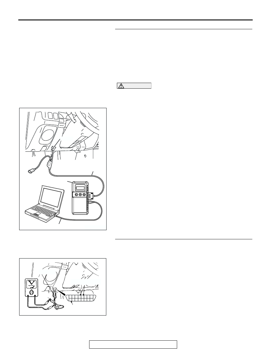
STEP 2. Check the ETACS-ECU input signal from the 
ignition switch (by using the pulse check) (by using 
MB991958).
Check the ETACS-ECU input signal [front door switches and 
ignition switch (IG1)] by using scan tool MB991958.
Check the input signals from the following switches:

• Driver's door switch

• Front passenger's door switch

• ignition switch

CAUTION

To prevent damage to scan tool MB991958, always turn the 
ignition switch to the "LOCK" (OFF) position before con-
necting or disconnecting scan tool MB991958.
(1) Connect scan tool MB991958 to the data link connector.
(2) Operate scan tool MB991958 as follows:

1. Select "SYSTEM SELECT."
2. Select "SWS."
3. Select "PULSE CHECK."

(3) Open the driver’s door or front passenger’s door.
(4) Turn the ignition switch (IG1) to ''ON'' position.
(5) Check that scan tool MB991958 sounds
Q: Does the tone alarm of scan tool MB991958 sound when 

the input signal enters?
YES : 
Replace the ETACS-ECU and then go to Step 11.
NO <Driver's door switch and passenger’s door switch 
input signal> : 
Go to Step 5.
NO <Ignition switch input signal> : Go to Step 7.

STEP 3. Check the ETACS-ECU input signal from the 
driver's door switch and passenger’s door switch (by 
using a voltmeter).
(1) Use special tool MB991529 to connect a voltmeter between 

ground terminal 4 or 5 and ETACS-ECU terminal 9 of the 
data link connector.

(2) Check that the voltmeter indicator deflects once when 

driver's door switch or passenger’s door switch operated 
<open (on)/depressed (off)>.

Q: Does the voltmeter indicator deflect?

YES : Go to Step 4.
NO :  Go to Step 5.

AK303629AB

MB991911

MB991827

MB991824 

16-PIN

7

6

5

4

3

2

1

14

13

12

11

10

9

8

16

15

AC004323

MB991529

GROUND TERMINAL

ETACS TERMINAL

AB

SUNROOF ASSEMBLY

TSB Revision

BODY

42-184

STEP 4. Check the input signal from the ignition switch (by 
using a voltmeter).
(1) Use special tool MB991529 to connect a voltmeter between 

ground terminal 4 or 5 and ETACS-ECU terminal 9 of the 
data link connector.

(2) Check that the voltmeter indicator deflects once when the 

ignition switch is operated <ACC - ON>.

Q: Does the voltmeter indicator deflect?

YES : Replace the ETACS-ECU and then go to Step 11.
NO :  Go to Step 7.

STEP 5. Check driver's door switch connector E-33 and 
front passenger’s door switch connector E-46 for loose, 
corroded or damaged terminals, or terminals pushed back 
in the connector.
Q: Are driver's door switch connector E-33 and front 

passenger’s door switch E-46 in good condition?
YES : 
Go to step 6.
NO :  Repair or replace the damaged components. Refer to 

GROUP 00E 

P.00E-2

, Harness Connector inspection. 

Then go to Step 11.

7

6

5

4

3

2

1

14

13

12

11

10

9

8

16

15

AC004323

MB991529

GROUND TERMINAL

ETACS TERMINAL

AB

AC004329AJ

E-46

E-33

CONNECTORS: E-33, E-46

COMPONENT SIDE

2 1

SUNROOF ASSEMBLY

TSB Revision

BODY

42-185

STEP 6. Check the front door switch.
(1) Remove the driver's door or fornt passenger’s door switch 

(Refer to 

P.52A-42

.).

(2) Follow the table to check the front door switches continuity.

TYPE1

TYPE2

Q: Is the front door switch in good condition?

YES : Go to Step 7 .
NO :  Replace front door switch, then go to Step 11. 

STEP 7. Check ETACS-ECU connector D-11 and D-26 for 
loose, corroded or damaged terminals, or terminals 
pushed back in the connector.
Q: Are ETACS-ECU connector D-11 and D-26 in good 

condition?
YES : 
Go to step 8.
NO :  Repair or replace the damaged components. Refer to 

GROUP 00E 

P.00E-2

, Harness Connector inspection. 

Then go to Step 11.

SWITCH 
POSITION

TESTER 
CONNECTION

SPECIFIED 
CONDITION

Released (ON)

− 2, 1 − 3, 2 − 3 Less than 2 ohms

Depressed (OFF) 1 

− 2, 1 − 3, 2 − 3 Open circuit 

SWITCH 
POSITION

TESTER 
CONNECTION

SPECIFIED 
CONDITION

Released (ON)

− 2 

Less than 2 ohms

Depressed (OFF) 1 

− 2 

Open circuit 

AC003906

TYPE 1

AB

1

2

3

OFF

ON

STROKE

AC003907

TYPE 2

1

2

ON

OFF

STROKE

AB

AC202080

1

4 3 2

5

7 6

8

9

11

12

10

21

22

28 27

24

30

25

31

32

26

29

23

JUNCTION BLOCK (REAR)

CONNECTOR: D-11, D-26

D-11

D-26 (B)

D-11 COMPONENT SIDE

D-26 COMPONENT SIDE

AC

SUNROOF ASSEMBLY

TSB Revision

BODY

42-186

STEP 8. Check the harness wire between ETACS-ECU 
connector D-11 (terminal No.9), D-26 (terminal No.26) and 
driver's door switch connectors E-33 (terminal No.2), front 
passenger’s side door switch connector E-46 (terminal 
No.2). 

AC202081

1

4 3 2

5

7 6

8

9

11

12

10

21

22

28 27

24

30

25

31

32

26

29

23

1
8

3

4

5

7 6

10

15

16

14

12

13

11

9

2

JUNCTION BLOCK (REAR)

CONNECTORS: D-11, D-14, D-26

D-11

D-26 (B)

D-11 COMPONENT SIDE

D-26 COMPONENT SIDE

AB

D-14 COMPONENT SIDE

D-14 (B)

AC202082

2 1

8

19

7

6

5

16

15

17 18

4

3

2

10 11 12 13

1
9

14

E-46

E-33

CONNECTORS: E-33, E-42, E-46

 E-33, E-46  COMPONENT SIDE

E-42

E-42

AB


Content   ..  480  481  482  483   ..