Mitsubishi Montero Sport (2004+). Manual - part 410
KNUCKLE
TSB Revision
FRONT AXLE
26-21
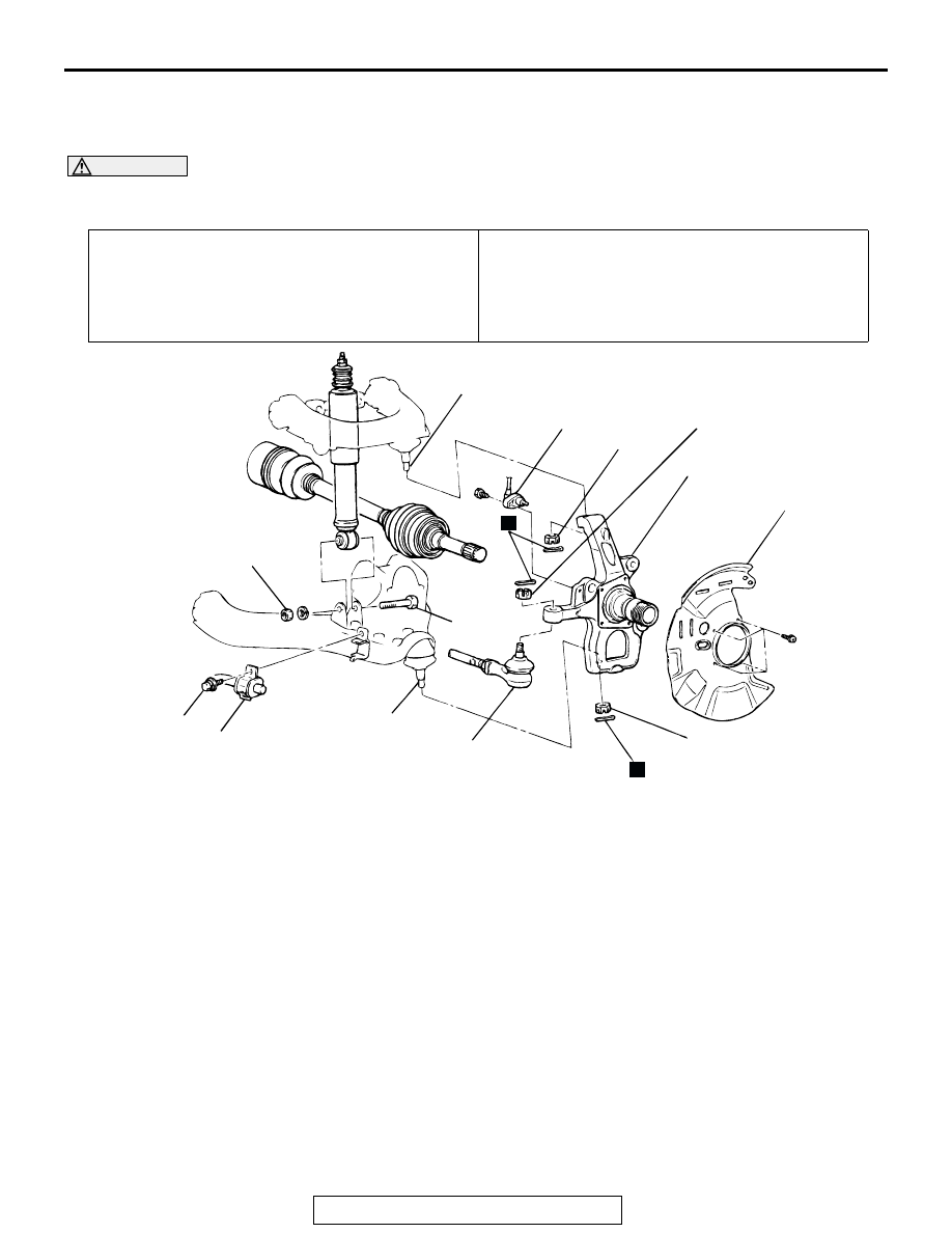
KNUCKLE
REMOVAL AND INSTALLATION
M1261002400195
CAUTION
*: Indicates parts which should be temporarily tightened, and then fully tightened with the vehicle on
the ground in the unladen condition.
Required Special Tool:
• MB991897: Ball Joint Remover
Pre-removal Operation
• Front Hub Assembly Removal (Refer to
Post-installation Operation
• Press the dust cover with a finger to check whether the
dust cover is cracked or damaged.
• Front Hub Assembly Installation (Refer to
• Wheel Alignment Check and Adjustment (Refer to
GROUP 33A, On-vehicle Service
AC004662 AC
12 N·m
106 in-lb
88 - 103 N·m*
65 - 76 ft-lb*
59 - 88 N·m
43 - 65 ft-lb
44 N·m
32 ft-lb
118 - 177 N·m
87 - 131 ft-lb
N
1
8
2
7
4
N
3
6
5
REMOVAL
STEPS
1. DUST
COVER
2. FRONT SPEED SENSOR
<VEHICLES WITH ABS> (REFER
TO GROUP 35B, WHEEL SPEED
SENSOR.)
3. STABILIZER BAR CONNECTION
4. SHOCK ABSORBER LOWER
MOUNTING BOLT
<<A>>
5. TIE ROD END CONNECTION
<<A>>
6. LOWER ARM BALL JOINT
CONNECTION
<<A>>
7. UPPER ARM BALL JOINT
CONNECTION
8. KNUCKLE
REMOVAL STEPS (Continued)