Mitsubishi Montero Sport (2004+). Manual - part 295


  Index      Mitsubishi     Mitsubishi Montero Sport - service repair manual 2004 year


Search            


Content   ..  293  294  295  296   ..


Mitsubishi Montero Sport (2004+). Manual - part 295


MULTIPORT FUEL INJECTION (MFI) DIAGNOSIS

TSB Revision

MULTIPORT FUEL INJECTION (MFI)

13A-593

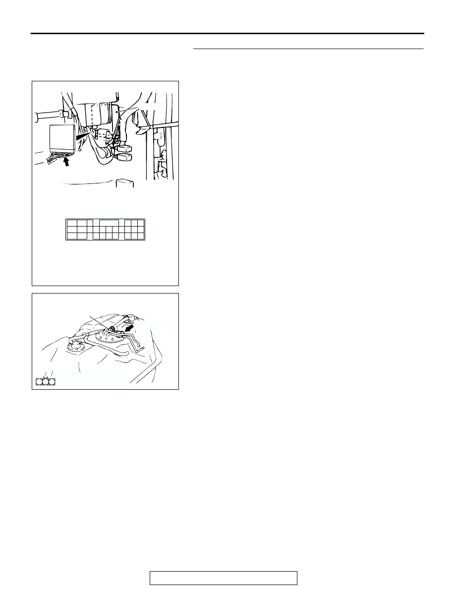
STEP 6. Check the harness wire for open circuit between 
PCM connector C-90 terminal 57 and fuel tank differential 
pressure sensor connector E-28 terminal 2 for damage.
Q: Are the harness wires in good condition?

YES : It can be assumed that this malfunction is intermittent. 

(Refer to GROUP 00, How to Use 
Troubleshooting/Inspection Service Points 

− How to 

Cope with Intermittent Malfunction 

P.00-7

). Then go 

to Step 16 .

NO :  Repair or replace the harness wire. Then go to 16 .

PCM

60

46

66

57

45

44

64

55 56

65

62 63

52 53

5051

61

42

59

48

41
47
58

43
49

54

AC202313

C-90 (GR)

AC

CONNECTOR: C-90

C-90 (GR)

C-90 HARNESS SIDE CONNECTOR 

AC002614

CONNECTOR: E-28

FUEL TANK
DIFFERENTIAL
PRESSURE
SENSOR

AH

E-28 (B)

2 1

3

E-28 HARNESS SIDE 
CONNECTOR

MULTIPORT FUEL INJECTION (MFI) DIAGNOSIS

TSB Revision

MULTIPORT FUEL INJECTION (MFI)

13A-594

STEP 7. Measure the output circuit voltage at PCM 
connector C-91 by backprobing. 
(1) Do not disconnect PCM connector C-91.

(2) Disconnect hose E from the evaporative emission canister 

side, and plug the hose.

(3) Turn the ignition switch to the "ON" position.

(4) Measure the voltage between terminal 92 and ground by 

backprobing.

• When the fuel cap is removed, the voltage should mea-

sure between 2.0 and 3.0 volts.

(5) Turn the ignition switch to the "LOCK" (OFF) position.
(6) Disconnect the evaporative emission system pressure 

pump, and reinstall the fuel cap.

(7) Connect hose E to the canister.
Q: Is the measured voltage between 2.0 and 3.0 volts?

YES : Go to Step 8 .
NO :  Go to Step 9 .

PCM

89
98

88
97

76 77

87

86

83
94

84
95

85

96

80
92

81
93

79

78
90 91

82

74

71 72 73

75

AC202312

CONNECTORS: C-91

AC

C-91 (GR)

C-91 HARNESS SIDE CONNECTOR

AC005140

HOSE E

AC

AC005153 AC

C-91 HARNESS CONNECTOR:
HARNESS SIDE 

MULTIPORT FUEL INJECTION (MFI) DIAGNOSIS

TSB Revision

MULTIPORT FUEL INJECTION (MFI)

13A-595

STEP 8. Check connectors C-91 at PCM and E-28 at fuel 
tank differential pressure sensor for loose, corroded or 
damaged terminals, or terminals pushed back in the 
connector.
Q: Are the connector and terminals in good condition?

YES : Go to Step 15 .
NO :  Repair or replace the damaged component. (Refer to 

GROUP 00E, Harness Connector Inspection 

P.00E-2

). Then go to Step 16 .

PCM

89
98

88
97

76 77

87

86

83
94

84
95

85

96

80
92

81
93

79

78
90 91

82

74

71 72 73

75

AC202312

CONNECTORS: C-91

AC

C-91 (GR)

C-91 HARNESS SIDE CONNECTOR

AC002614

CONNECTOR: E-28

FUEL TANK
DIFFERENTIAL
PRESSURE
SENSOR

AH

E-28 (B)

2 1

3

E-28 HARNESS SIDE 
CONNECTOR

MULTIPORT FUEL INJECTION (MFI) DIAGNOSIS

TSB Revision

MULTIPORT FUEL INJECTION (MFI)

13A-596

STEP 9. Check connectors E-44, C-16, at intermediate 
connector and C-91 at PCM and E-28 at fuel tank 
differential pressure sensor for loose, corroded or 
damaged terminals, or terminals pushed back in the 
connector.

AC203242 AC

CONNECTOR: E-44

E-44

E-44 MALE SIDE CONNECTOR

20

19

7

16

6

17

15

5

14

18

8

4

11

3

12

2

9

1

10

13

AC203236 AC

CONNECTOR: C-16

C-16

22

2021

10

9

8

1718

6 7

19

1415

4 5

1112

1 2 3

13

16

C-16 MALE SIDE 
CONNECTOR

PCM

89
98

88
97

76 77

87

86

83
94

84
95

85

96

80
92

81
93

79

78
90 91

82

74

71 72 73

75

AC202312

CONNECTORS: C-91

AC

C-91 (GR)

C-91 HARNESS SIDE CONNECTOR


Content   ..  293  294  295  296   ..