Mitsubishi Montero Sport (2004+). Manual - part 293


  Index      Mitsubishi     Mitsubishi Montero Sport - service repair manual 2004 year


Search            


Content   ..  291  292  293  294   ..


Mitsubishi Montero Sport (2004+). Manual - part 293


MULTIPORT FUEL INJECTION (MFI) DIAGNOSIS

TSB Revision

MULTIPORT FUEL INJECTION (MFI)

13A-585

.

CIRCUIT OPERATION

• The PCM (terminal 46) supplies a 5-volt refer-

ence signal to the fuel tank differential pressure 
sensor (terminal 3). The fuel tank differential 
pressure sensor (terminal 2) is grounded through 
the PCM (terminal 57).

• The fuel tank differential pressure sensor (termi-

nal 1) returns a voltage signal to the PCM (termi-
nal 92) that is proportional to the pressure in the 
fuel tank.

.

TECHNICAL DESCRIPTION

• The PCM monitors the fuel tank differential pres-

sure sensor output voltage.

• The PCM determines whether the fuel tank differ-

ential pressure sensor signal voltage is within 
normal operating parameters.

NOTE: In rare cases, this DTC may be also set 
under some fuel and driving conditions regardless of 
the fuel pressure sensor output voltage when the fuel 
system is clogged.

.

DESCRIPTIONS OF MONITOR METHODS

• Compare purge solenoid status with fuel tank dif-

ferential pressure sensor output voltage.

.

MONITOR EXECUTION

• Continuous.

.

MONITOR EXECUTION CONDITIONS (Other 
Monitor and Sensor)

Other Monitor (There is no temporary DTC stored 

in memory for the item monitored below)

• Evaporative emission purge solenoid monitor

• Evaporative emission ventilation solenoid monitor

 Sensor (The sensors below are determined to be 

normal)

• Volume airflow sensor

• Barometric pressure sensor

• Intake air temperature sensor

• Engine coolant temperature sensor

.

PCM

C-90 (GR) C-91 (GR)

AC203152 AB

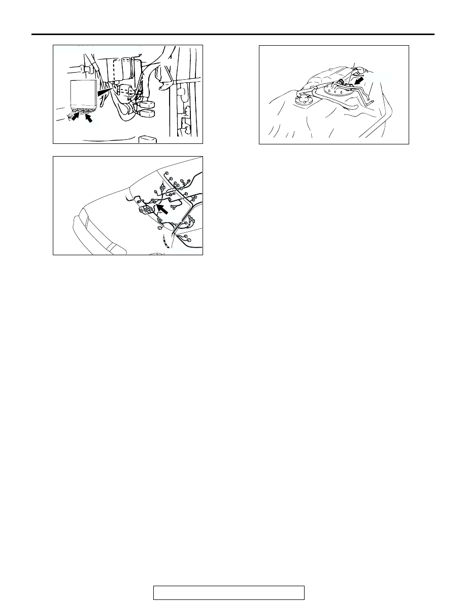
CONNECTORS: C-90, C-91

AC002614

CONNECTOR: E-28

FUEL TANK DIFFERENTIAL
PRESSURE SENSOR

AE

E-28 (B)

AC203242

CONNECTOR: E-44

AB

E-44

MULTIPORT FUEL INJECTION (MFI) DIAGNOSIS

TSB Revision

MULTIPORT FUEL INJECTION (MFI)

13A-586

LOGIC FLOW CHARTS (Monitor Sequence)

.

DTC SET CONDITIONS

Test Conditions: For Test to Run

• Intake air temperature is between 5 °C (41 °F) 

and 45 

°C (113 °F) or greater.

• Engine speed is greater than 1,600 r/min.

• Volumetric efficiency is between 25 and 80 per-

cent.

Judgment Criteria

• When the evaporative emission purge solenoid is 

fully operational (100 percent ratio), the fuel dif-
ferential pressure sensor output voltage remains 
4.0 volts or greater for ten seconds.

.

OBD-ll DRIVE CYCLE PATTERN
Refer to Diagnostic Function 

− OBD-ll Drive Cycle − 

Procedure 1 

− Evaporative Emission System Leak 

Monitor 

P.13A-4

.

.

TROUBLESHOOTING HINTS (The most likely 
causes for this code to be set are:)

• Malfunction of the fuel tank differential pressure 

sensor.

• A damaged harness in the fuel tank differential 

pressure sensor circuit.

• Malfunction of the PCM.

.

NO

YES 

CONTINUOUS

FAILURE FOR 10 SECS

START


END


NO 

NO

NO

YES


YES 


YES   

MALFUNCTION

GOOD


MONITORING


CONDITIONS


OUTPUT VOLTAGE


< 1.0V

OUTPUT VOLTAGE


> 4.0V


AC306648

RANGE CHECK - MIN/MAX

MULTIPORT FUEL INJECTION (MFI) DIAGNOSIS

TSB Revision

MULTIPORT FUEL INJECTION (MFI)

13A-587

OVERVIEW OF TROUBLESHOOTING

•  DTC P0453 can be set by a faulty fuel tank differ-

ential pressure sensor or related circuit, or PCM 
failure.

• To check a system blockage, do a performance 

test which uses a mechanical vacuum gauge and 
scan tool MB991958 set on the fuel tank differen-
tial pressure sensor (TANK PRS SNSR 73).

The mechanical gauge reading is used to verify 
scan tool MB991958 reading.
A comparison of the mechanical gauge with the 
reading on scan tool MB991958 will locate a 
problem in the system.

DIAGNOSIS

Required Special Tools:

• MB991958: Scan tool (MUT-III sub assembly)

• MB991824: V.C.I.

• MB991827: MUT-III USB cable

• MB991911: MUT-III main harness B

• MB991658: Test harness set

MULTIPORT FUEL INJECTION (MFI) DIAGNOSIS

TSB Revision

MULTIPORT FUEL INJECTION (MFI)

13A-588

STEP 1. Using scan tool MB991958, check data list item 73: 
Fuel Tank Differential Pressure Sensor.

CAUTION

To prevent damage to scan tool MB991958, always turn the 
ignition switch to the "LOCK" (OFF) position before con-
necting or disconnecting scan tool MB991502.
(1) Connect scan tool MB991958 to the data link connector.

(2) Disconnect hose E from the evaporative emission canister 

side, and plug the hose.

(3) Turn the ignition switch to the "ON" position.
(4) Remove the fuel cap.
(5) Set scan tool MB991958 to the data reading mode.

• Item 73, Fuel Tank Differential Pressure Sensor.

• The fuel tank pressures reading on the scan tool 

should be 

−3.3 to 3.3 kPa (−0.97 to 0.97 inHg).

(6) Connect an evaporative emission system pressure pump to 

the fuel filler neck and pressurize the fuel tank.

• The fuel tank pressure reading should increase.

(7) Turn the ignition switch to the "LOCK" (OFF) position. Then 

disconnect scan tool MB991958.

(8) Disconnect the evaporative emission system pressure 

pump, and reinstall the fuel cap.

(9) Connect hose E to the canister.
Q: Is the fuel tank pressure between 

3.3 and 3.3 kPa 

(

0.97 and 0.97 inHg)?

YES : It can be assumed that this malfunction is intermittent. 

(Refer to GROUP 00, How to Use 
Troubleshooting/Inspection Service Points 

− How to 

Cope with Intermittent Malfunction 

P.00-7

). Then go 

to Step 16 .

NO :  Go to Step 2 .

AK303629AB

MB991911

MB991827

MB991824 

16-PIN

AC005140

HOSE E

AC

ACX01358


Content   ..  291  292  293  294   ..