Mitsubishi Montero Sport (2004+). Manual - part 294


  Index      Mitsubishi     Mitsubishi Montero Sport - service repair manual 2004 year


Search            


Content   ..  292  293  294  295   ..


Mitsubishi Montero Sport (2004+). Manual - part 294


MULTIPORT FUEL INJECTION (MFI) DIAGNOSIS

TSB Revision

MULTIPORT FUEL INJECTION (MFI)

13A-589

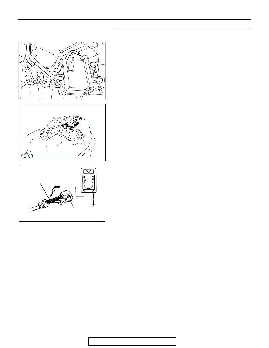
STEP 2. Measure the sensor output voltage at fuel tank 
differential pressure sensor connector E- 28.
(1) Disconnect hose E from the evaporative emission canister 

side, and plug the hose.

(2) Remove the fuel tank mounting nuts, tilt the fuel tank.

(3) Disconnect fuel tank differential pressure sensor connector 

E-28.

(4) Connect special tool MB991658 between pressure sensor 

connector terminal 1, 2 and 3.

(5) Turn the ignition switch to the "ON" position.
(6) Remove the fuel cap.
(7) Measure the voltage between terminal 1 and ground.

• The measured voltage should measure between 2.0 

and 3.0 volts.

(8) Turn the ignition switch to the "LOCK" (OFF) position.
(9) Disconnect the evaporative emission system pressure 

pump, and reinstall the fuel cap.

(10)Connect hose E to the canister.
Q: Is the measured voltage between 2.0 and 3.0 volts?

YES : Go to Step 7 .
NO :  Go to Step 3 .

AC005140

HOSE E

AC

AC002614

CONNECTOR: E-28

FUEL TANK
DIFFERENTIAL
PRESSURE
SENSOR

AH

E-28 (B)

2 1

3

E-28 HARNESS SIDE 
CONNECTOR

AC002081AB

MB991658

FUEL TANK DIFFERENTIAL 
PRESSURE SENSOR

MULTIPORT FUEL INJECTION (MFI) DIAGNOSIS

TSB Revision

MULTIPORT FUEL INJECTION (MFI)

13A-590

STEP 3. Measure the 5-volt supply circuit voltage at fuel 
tank differential pressure sensor connector E-28.
(1) Disconnect fuel tank differential pressure sensor connector 

E-28.

(2) Connect special tool MB991658 between pressure sensor 

connector terminal 1, 2 and 3.

(3) Turn the ignition switch to the "ON" position.
(4) Measure the voltage between terminal 3 and ground.

• Voltage should measure between 4.7 and 5.1 volts.

(5) Turn the ignition switch to the "LOCK" (OFF) position.
Q: Is the measured voltage between 4.7 and 5.1 volts?

YES : Go to Step 4 .
NO :  Go to Step 10 .

STEP 4. Measure the ground circuit voltage at fuel tank 
differential pressure sensor connector E-28. 
(1) Disconnect fuel tank differential pressure sensor connector 

E-28.

(2) Connect special tool MB991658 to connect terminal 3 of the 

disconnected sensor connector and those of the harness 
side connector respectively.

(3) Turn the ignition switch to the "ON" position.
(4) Measure the voltage at the fuel tank differential pressure 

sensor side connector between terminal 2 and ground.

• Voltage should measure 0.5 volt or less.

(5) Turn the ignition switch to the "LOCK" (OFF) position.
Q: Is the measured voltage 0.5 volt or less?

YES : Go to Step 5 .
NO :  Go to Step 12 .

AC002614

CONNECTOR: E-28

FUEL TANK
DIFFERENTIAL
PRESSURE
SENSOR

AH

E-28 (B)

2 1

3

E-28 HARNESS SIDE 
CONNECTOR

AC002081AB

MB991658

FUEL TANK DIFFERENTIAL 
PRESSURE SENSOR

AC002614

CONNECTOR: E-28

FUEL TANK
DIFFERENTIAL
PRESSURE
SENSOR

AH

E-28 (B)

2 1

3

E-28 HARNESS SIDE 
CONNECTOR

AC002081AB

MB991658

FUEL TANK DIFFERENTIAL 
PRESSURE SENSOR

MULTIPORT FUEL INJECTION (MFI) DIAGNOSIS

TSB Revision

MULTIPORT FUEL INJECTION (MFI)

13A-591

STEP 5. Check connectors E-44, C-16, C-71 at intermediate 
connector and C-90 at PCM and E-28 at fuel tank 
differential pressure sensor for loose, corroded or 
damaged terminals, or terminals pushed back in the 
connector.

AC203242 AC

CONNECTOR: E-44

E-44

E-44 MALE SIDE CONNECTOR

20

19

7

16

6

17

15

5

14

18

8

4

11

3

12

2

9

1

10

13

AC203236 AC

CONNECTOR: C-16

C-16

22

2021

10

9

8

1718

6 7

19

1415

4 5

1112

1 2 3

13

16

C-16 MALE SIDE 
CONNECTOR

AC203241

CONNECTOR: C-71

AD

C-71

9 10

8

6 7

31 32

30

29

18 19 20 21

5

4

2

1

3

27

26

24

23

25

12 13 14 15 16 17

28

11
22
33

C-71 JOINT CONNECTOR

AC002614

CONNECTOR: E-28

FUEL TANK
DIFFERENTIAL
PRESSURE
SENSOR

AH

E-28 (B)

2 1

3

E-28 HARNESS SIDE 
CONNECTOR

MULTIPORT FUEL INJECTION (MFI) DIAGNOSIS

TSB Revision

MULTIPORT FUEL INJECTION (MFI)

13A-592

Q: Are the connectors in good condition?

YES : Go to Step 6 .
NO :  Repair or replace the damaged components. (Refer to 

GROUP 00E, Harness Connector Inspection 

P.00E-2

). Then go to Step 16 .

PCM

60

46

66

57

45

44

64

55 56

65

62 63

52 53

5051

61

42

59

48

41
47
58

43
49

54

AC202313

C-90 (GR)

AC

CONNECTOR: C-90

C-90 (GR)

C-90 HARNESS SIDE CONNECTOR 


Content   ..  292  293  294  295   ..