Mitsubishi Montero Sport (2004+). Manual - part 257


  Index      Mitsubishi     Mitsubishi Montero Sport - service repair manual 2004 year


Search            


Content   ..  255  256  257  258   ..


Mitsubishi Montero Sport (2004+). Manual - part 257


MULTIPORT FUEL INJECTION (MFI) DIAGNOSIS

TSB Revision

MULTIPORT FUEL INJECTION (MFI)

13A-441

Judgement Criteria (change in the angular accel-

eration of the crankshaft is used for misfire 
detection.)

• Misfire has occurred more frequently then 

allowed during the last 200 revolutions [when the 
catalyst temperature is higher than 950

°C 

(1742

°F)].

or

• Misfire has occurred in 20 or more of the last 

1,000 revolutions (corresponding to 1.5 times the 
limit of emission standard).

.

OBD-II DRIVE CYCLE PATTERN
Refer to Diagnostic Function 

− OBD-II Drive Cycle − 

Procedure 6 

− Other Monitor 

P.13A-4

.

.

TROUBLESHOOTING HINTS (The most likely 
causes for this code to be set are: )

• Ignition system related part(s) failed.

• Poor crankshaft position sensor.

• Low compression pressure.

• Skipping of timing belt teeth.

• EGR system and EGR valve failed.

• Harness damage in injector circuit, or connector 

damage.

• Injector failed.

• PCM failed.

DIAGNOSIS

Required Special Tools:

• MB991958: Scan Tool (MUT-III Sub Assembly)

• MB991824: V.C.I

• MB991827: USB Cable

• MB991911: Main Harness B

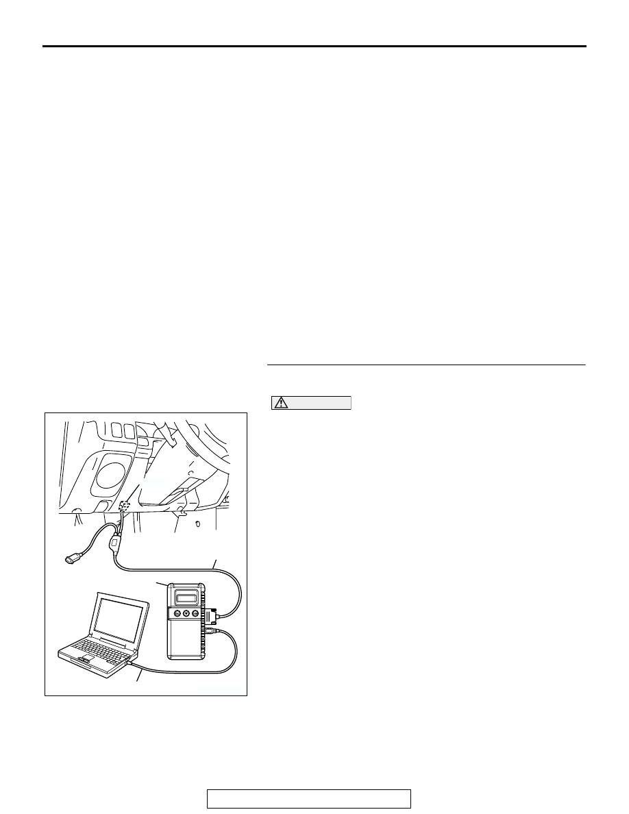
STEP 1. Using scan tool MB991958, check data list item 22: 
Crankshaft Position Sensor.

CAUTION

To prevent damage to scan tool MB991958, always turn the 
ignition switch to the "LOCK" (OFF) position before con-
necting or disconnecting scan tool MB991958.
(1) Connect scan tool MB991958 to the data link connector.
(2) Start the engine and run at idle.
(3) Set scan tool MB991958 to the data reading mode for item 

22, Crankshaft Position Sensor.

(4) Check the waveform of the crankshaft position sensor while 

keeping the engine speed constant.

• The pulse width should be constant.

(5) Turn the ignition switch to "LOCK" (OFF) position.
Q: Is the sensor operating properly?

YES : Go to Step 2.
NO :  Refer to, DTC P0335 

− Crankshaft Position Sensor 

Circuit Malfunction 

P.13A-452

.

AK303629AB

MB991911

MB991827

MB991824 

16-PIN

MULTIPORT FUEL INJECTION (MFI) DIAGNOSIS

TSB Revision

MULTIPORT FUEL INJECTION (MFI)

13A-442

STEP 2. Using scan tool MB991958, check data list item 81 
<bank 1> and 83 <bank 2>: Long-Term Fuel Compensation 
(trim).
(1) Start the engine and run at idle.
(2) Set scan tool MB991958 to the data reading mode for item 

81 <bank 1> and 83 <bank 2>, Long-Term Fuel 
Compensation (trim) Bank 1.

• The fuel trim should be between −12.5 and +12.5 when 

the load is 2,500 r/min (during closed loop) after the 
engine is warmed.

(3) Turn the ignition switch to "LOCK" (OFF) position.
Q: Is the specification normal?

YES : Go to Step 3.
NO :  Refer to, DTC P0171 

− System too Lean (bank 1) 

P.13A-372

, DTC P0172 

− System too Rich (bank 1) 

P.13A-381

, DTC P0174 

− System too Lean (bank 2) 

P.13A-387

, DTC P0175 

− System too Rich (bank 2) 

P.13A-396

.

STEP 3. Using scan tool MB991958, check data list item 82 
<bank 1> and 84 <bank 2>: Short-Term Fuel Compensation 
(trim) Bank 1.
(1) Start the engine and run at idle.
(2) Set scan tool MB991958 to the data reading mode for item 

82 <bank 1> and 84 <bank 2>, Short-Term Fuel 
Compensation (trim) Bank 1.

• The fuel trim should be between −7.4 and +7.4 when the 

load is 2,500 r/min (during closed loop) after the engine 
is warmed.

(3) Turn the ignition switch to "LOCK" (OFF) position.
Q: Is the specification normal?

YES : Go to Step 4.
NO :  Refer to, DTC P0171 

− System too Lean (bank 1) 

P.13A-372

, DTC P0172 

− System too Rich (bank 1) 

P.13A-381

, DTC P0174 

− System too Lean (bank 2) 

P.13A-387

, DTC P0175 

− System too Rich (bank 2) 

P.13A-396

.

AK303629AB

MB991911

MB991827

MB991824 

16-PIN

AK303629AB

MB991911

MB991827

MB991824 

16-PIN

MULTIPORT FUEL INJECTION (MFI) DIAGNOSIS

TSB Revision

MULTIPORT FUEL INJECTION (MFI)

13A-443

STEP 4. Check the ignition coil spark.
(1) Check each ignition coil spark.
(2) Remove the intake manifold.
(3) Remove the spark plug and connect to the spark plug 

cable.

(4) Ground the spark plug side electrode securely.

• When the engine is cranked, the spark plug should 

spark.

Q: Did it spark?

YES : Go to Step 7.
NO :  Go to Step 5.

STEP 5. Check the spark plugs.

CAUTION

Do not attempt to adjust the gap of the iridium plug. Clean-
ing of the iridium plug may result in damage to the iridium 
and platinum tips. Therefore, if carbon deposits must be 
removed, use a plug cleaner and complete cleaning within 
20 seconds to protect the electrode. Do not use a wire 
brush.
(1) Check the plug gap and replace if the limit is exceeded.

Standard value: 1.0 

 1.1 mm (0.039  0.043 inch)

Limit: 1.3 mm (0.051 inch)

Q: Is the plug gap at the standard value?

YES : Go to Step 6.
NO :  Replace the faulty spark plug. Then go to Step 13.

STEP 6. Check the spark plug cable.
(1) Check the cap and coating for cracks.
(2) Measure the resistance.

Limit: maximum 22 k

Q: Is the measured resistance less than 22 k

?

YES : Refer to, INSPECTION PROCEDURE 31 

− Ignition 

Circuit System 

P.13A-828

.

NO :  Replace the faulty spark plug cable. Then go to Step 

13.

AKX00432

SPARK PLUG

AB

AKX01327AB

IRIDIUM
TIP

PLATINUM
TIP

AKX00382

MULTIPORT FUEL INJECTION (MFI) DIAGNOSIS

TSB Revision

MULTIPORT FUEL INJECTION (MFI)

13A-444

STEP 7. Check the injector.
(1) Disconnect the injector connector.

(2) Measure the resistance between each injector side 

connector terminal No. 1 and No. 2.

Standard value: 13 

 16 ohms [at 20°C (68°F)]

Q: Is the resistance between 13 and 16 ohms [at 20

°

(68

°F)]?

YES : Go to Step 8.
NO :  Replace the faulty injector. Then go to Step 13.

STEP 8. Check connectors A-70, A-71, A-72, A-73, A-74, 
A-75 at injector and connector A-04 at injector 
intermediate connector for damage.
Q: Is the connector in good condition?

YES : Go to Step 9.
NO :  Repair or replace the faulty injector. Refer to GROUP 

00E, Harness Connector Inspection 

P.00E-2

. Then go 

to Step 13.

AK200022

1

2

AB

CONNECTORS: A-70, A-71, A-72, A-73, A-74, 
                            A-75

A-70(GR)

A-71(GR)

A-72(GR)

HARNESS CONNECTOR: 
COMPONENT SIDE

A-73(GR)

A-74(GR)

A-75(GR)

AK000456

1 2

INJECTOR SIDE
CONNECTOR

AB

AK200022

1

2

AB

CONNECTORS: A-70, A-71, A-72, A-73, A-74, 
                            A-75

A-70(GR)

A-71(GR)

A-72(GR)

HARNESS CONNECTOR: 
COMPONENT SIDE

A-73(GR)

A-74(GR)

A-75(GR)

AK200014

7

2 1
6 5

4 3
8

CONNECTOR: A-04

AB

FEMALE SIDE 
CONNECTOR

A-04(B)


Content   ..  255  256  257  258   ..